
Industrial robot

a robot and torsional rigid technology, applied in the field of industrial robots, can solve the problems of wear and dissonance, torsional rigid bushing wear, breaking force, etc., and achieve the effects of low friction, minimal friction, and effective and fast torsional rigid bushings

Inactive Publication Date: 2007-03-13
ABB (SCHWEIZ) AG
View PDF7 Cites 51 Cited by
  • Summary
  • Abstract
  • Description
  • Claims
  • Application Information

AI Technical Summary

Benefits of technology

[0006]The present invention aims to achieve a device for an industrial robot that is more effective and faster than conventional designs. The objective of the invention is, for a telescopic arm, to allow a low friction moment-transferring movement that is free of loose play and that is parallel. One goal of the present invention is thus to be able to perform a rotational movement in space with minimal friction, without loose play and with maximum rigidity with an arm system for an industrial robot. The rotational movement should be able to be performed at high speeds and acceleration and with relatively large moments.
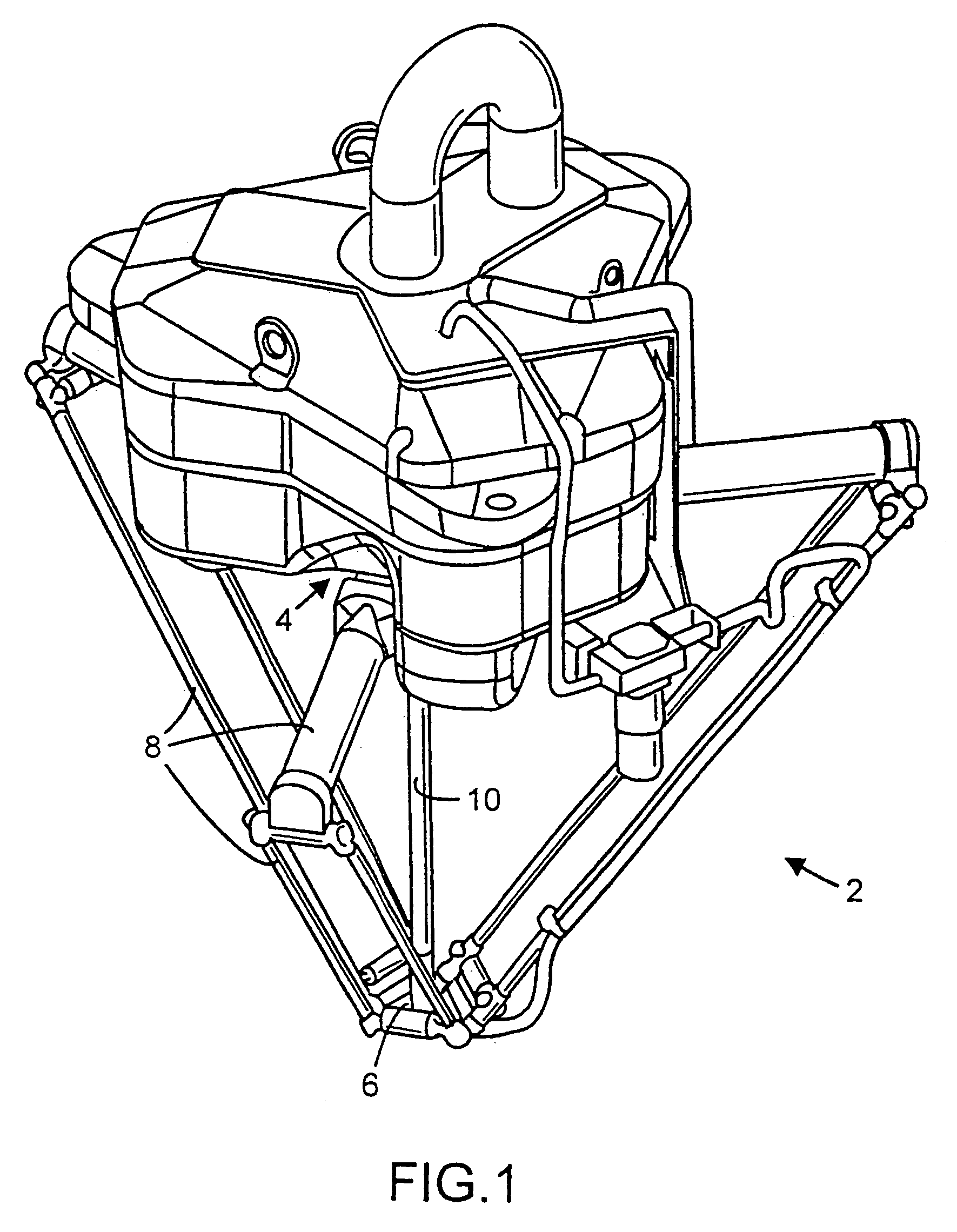
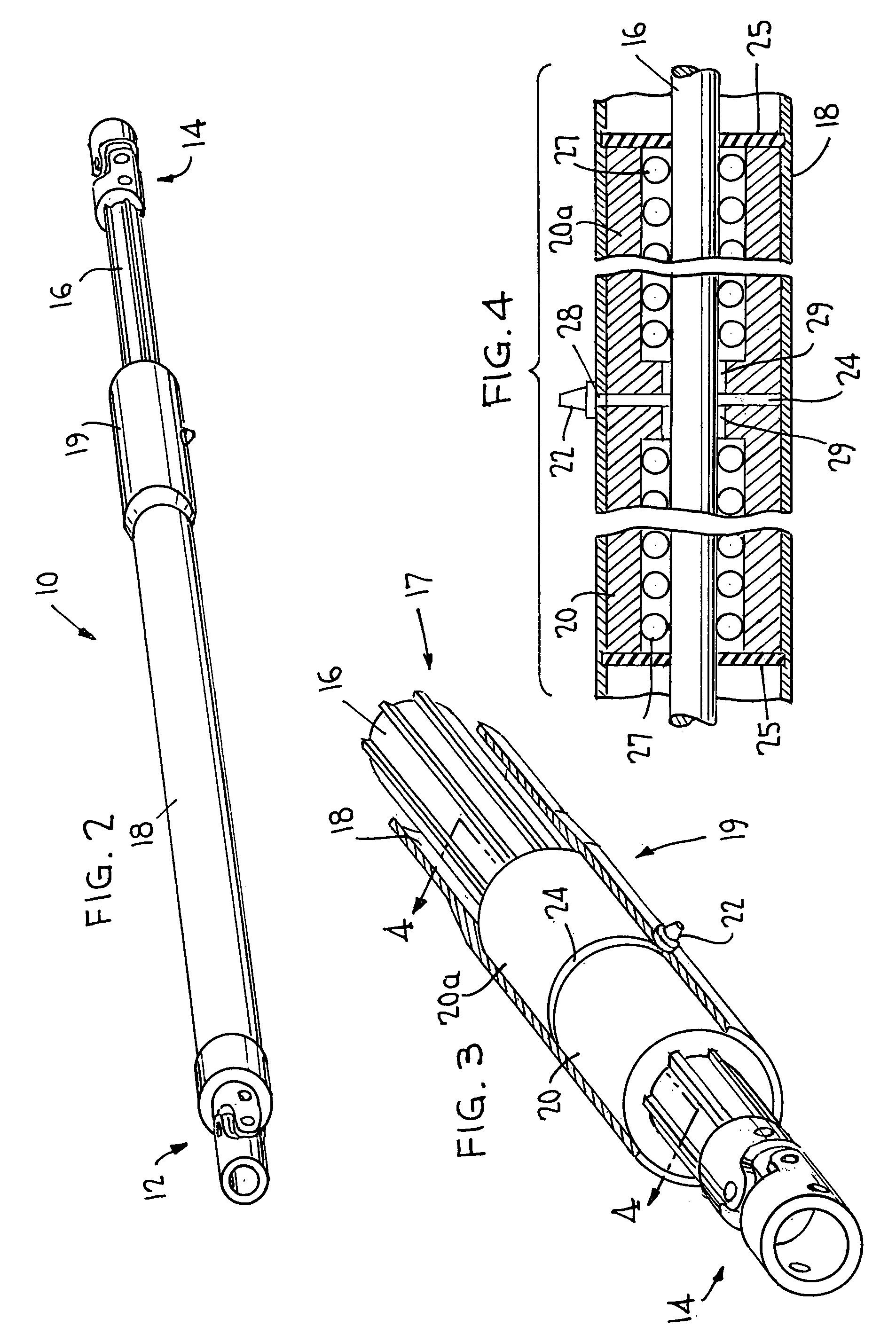
[0007]The solution is achieved by an industrial robot with the characteristics set forth in one or more of the appended claims. More specifically, the present invention relates to an industrial robot according to the delta concept with an arm system intended to rotate in space and that comprises a base section, a moveable plate, several multi-jointed pull rods and a telescopic axle arranged between the base section and the moveable plate, where opposite ends of the pull rods and the telescopic axle are connected with the base section and the moveable plate respectively, and where the telescopic axle comprises an inner axle and an outer tube arranged on the inner axle and displaceable in a longitudinal direction, where a pair of end-to-end torsional rigid bushings are arranged in a stationary manner on the outer tube in which the inner axle is mounted to be displaceable. One advantage with this solution is that a very torsional rigid design is achieved where a telescopic axle with a low friction moment-transferring movement that is free of loose play and parallel is obtained. The design can handle large moments in excess of 1 Nm and linear speeds of up to 10 m / s. A further advantage is that friction and loose play are minimized, whereby the robot can perform rotational movements with high speed and great precision.
[0008]The present invention also includes a guiding device for a telescopic axle for an industrial robot according to the delta concept. The inner axle usually has a free axle end that is not fixed. When the telescopic axle decreases / increases in length, the inner axle moves parallel with the outer tube. There is then a risk that the inner axle will come into contact with the inside of the outer tube, which causes wear and dissonance. A further disadvantage is that a loading, a breaking force, occurs on the said torsional rigid bushing in that the inner axle tilts around the bushing. This problem is solved according to the present invention with an industrial robot which provides an arm system intended to rotate in space that comprises a base section, a moveable plate, several multi-jointed pull rods and a telescopic axle arranged between the base section and the moveable plate, where opposite ends of the pull rods and the telescopic axle are connected with the base section and the moveable plate respectively, and where the telescopic axle comprises an inner axle and an outer tube arranged on the inner axle and displaceable in a longitudinal direction, where a torsional rigid bushing in a stationary manner on the outer tube in which the inner axle is mounted to be displaceable is arranged, and also a guiding device that is firmly attached to the inner axle, whereby one part of the guiding device is arranged to abut the inside of the outer tube. One advantage with this solution is that a telescopic axle is achieved that eliminates problems of wear and dissonance, at the same time as a very torosional rigid design with reduced friction and loose play is achieved. Due to the solution with the guiding device, the parts of the telescopic arm, the inner axle and the outer tube, move parallel in relation to one another. The inner axle is prevented from tilting and causing a breaking force on the bushing.

Problems solved by technology

There is then a risk that the inner axle will come into contact with the inside of the outer tube, which causes wear and dissonance.
A further disadvantage is that a loading, a breaking force, occurs on the said torsional rigid bushing in that the inner axle tilts around the bushing.

Method used


Image

  • Industrial robot
  • Industrial robot
  • Industrial robot

Examples


Embodiment Construction

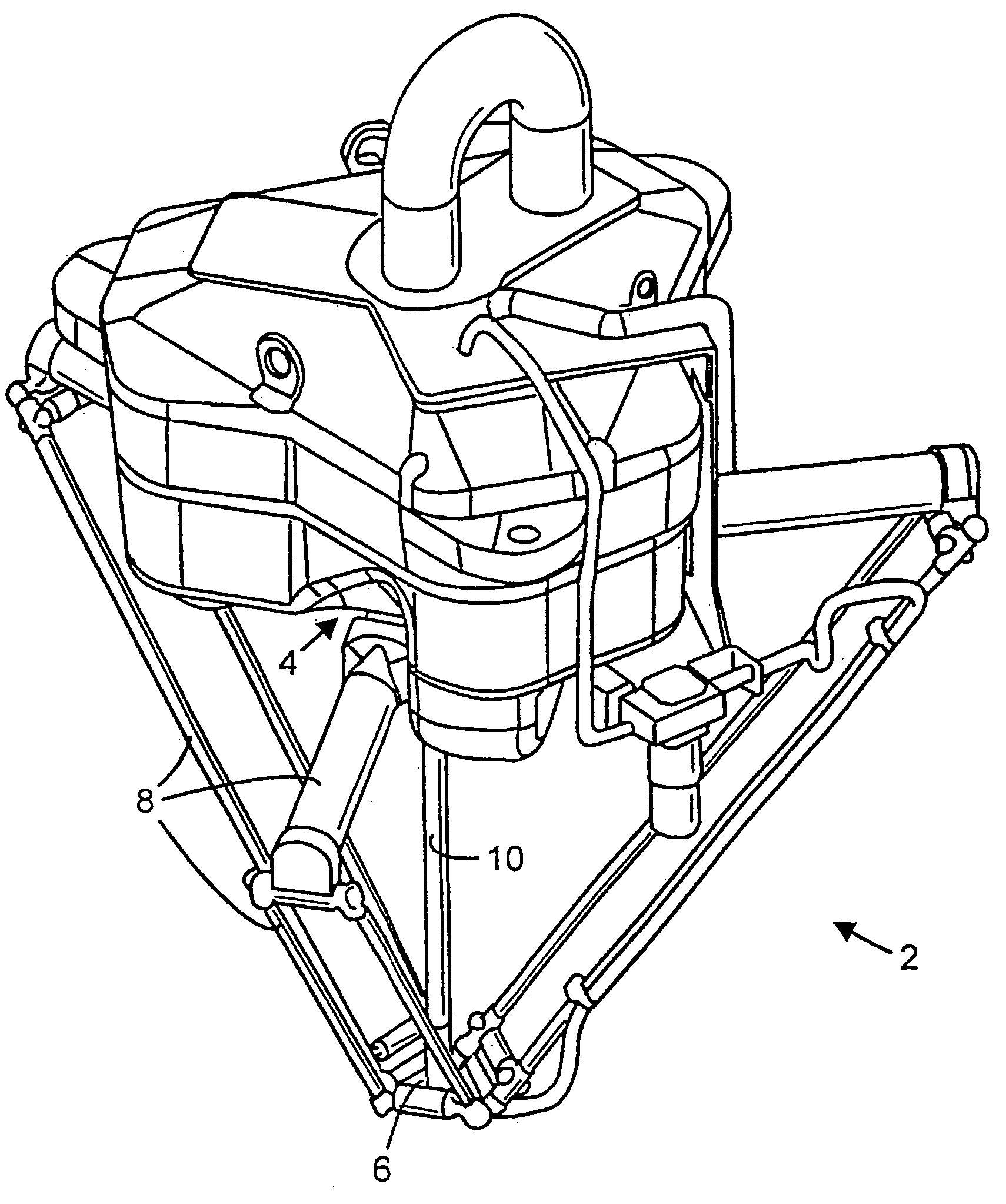
[0022]FIG. 1 shows an industrial robot according to the delta concept. The industrial robot is designed with an amt system 2 intended to rotate in the space. A number of jointed pull rods 8 are arranged on a moveable plate 6 at their end sections. The jointed pull rods are arranged to a generally designated base section 4 of the robot at their opposite end sections. A tool is intended to be arranged on the moveable plate 6. A fourth axle in the font of a telescopic axle 10 is arranged between the base section and the moveable plate where the opposite ends of the telescopic axle 10 (see FIG. 2) and the respective pull rods 8 are connected with the base section and the moveable plate respectively. The task of the telescopic axle is to act as a driving axle from a motor in the robot structure to a tool arranged on the moveable plate. At one end, the telescopic axle is arranged in a stationary manner on base section 4 and at its other end is able to move freely when it is arranged at mo...


PUM


Abstract

An industrial delta robot with an arm system rotatable in space and including a base section, a moveable plate, several multi-jointed pull rods and a telescopic axle arranged between the base section and the moveable plate, opposite ends of the pull rods and of the telescopic axle being connected with the base section and the moveable plate respectively, and the telescopic axle comprising an inner axle and an outer tube arranged on the inner axle and displaceable in a longitudinal direction where a pair of end-to-end torsional rigid bushings are arranged in a stationary manner on the outer tube in which the inner axle is mounted to be displaceable, the bushings being spaced apart at confronting inner ends to form a transversely extending lubrication pocket for continuous lubrication of the inner axle during movement relative to the bushings.

Description

RELATED APPLICATION[0001]This Continuation-In-Part application claims benefit of priority of U.S. application Ser. No. 09 / 857,349, filed Jul. 30, 2001 now abandoned.TECHNICAL FIELD[0002]The present invention relates to an industrial robot according to the delta concept with an arm system. The present invention also relates to a pair of end-to-end torsional rigid bushings and, in an alternative solution, to the bushings and a guiding device on a telescopic axle for an industrial robot according to the delta concept, as well as to the use of the bushings and alternatively the guiding device for an industrial robot. The present invention also relates to a method for an industrial robot according to the delta concept with an arm system intended to rotate in space.BACKGROUND[0003]The use of industrial robots for the flexible automation of industrial processes has become increasingly common for replacing time consuming, monotonous and difficult work. Such work can, for example, be transfe...

Claims


Application Information

Patent Timeline
IPC IPC(8): B25J17/00B23Q1/54B25J17/02B25J18/02
CPCB23Q1/5462B25J17/0266B25J18/025B25J9/0051B25J19/0062Y10T74/20305Y10T74/20317
Inventor PERSSON, FREDRIKHVITTFELDT, HAKANLARSSON, JANMIKAELSSON, PIERRE
Owner ABB (SCHWEIZ) AG
Learn More