Motor cooler for submersible pump

a submersible pump and motor cooler technology, applied in the direction of fluid removal, insulation, borehole/well accessories, etc., can solve the problems of gas blocking or locking, early motor failure, and electric motors that are typically used in such systems generate considerable heat, and achieve the effect of reducing scaling

Active Publication Date: 2007-03-13
BAKER HUGHES INC
View PDF19 Cites 39 Cited by
  • Summary
  • Abstract
  • Description
  • Claims
  • Application Information

AI Technical Summary

Benefits of technology

[0005]It is therefore an object of the invention to provide an electrical submersible pump (ESP) that circulates fluid past the motor of the pumping unit. By circulating fluid past the motor, the fluid provides forced convection cooling. Additionally, the motor cooler of the invention forces fluid through the annulus between the motor and the well casing, which results in decreased scaling as compared to pulling or drawing the fluid through the annulus.
[0007]An example flow director is a shroud that sealingly engages the electrical submersible pump at an upper end of the shroud and directs fluid received from the motor cooler pump output port downwardly past the motor, i.e., the shroud configuration may be termed a “positive reverse flow shroud setup”. Fluid then flows upwardly outside of the shroud. Utilizing the motor cooler of the invention reduces the potential for scale deposits because the pressure drop normally associated with a typical shrouded ESP is eliminated. Advantages include maximization of production from oil, water, and gas wells, reduced potential for scale formation, and reduced gas entry into the pumping system.

Problems solved by technology

The electric motor that is typically used in such systems generates considerable heat.
Insufficient fluid velocity will cause the motor to overheat and may lead to early motor failure.
The presence of gas can be significant because gas inhibits the pump from producing liquid, which may result in gas blocking, or locking.
Equipment failure may result if a unit is not shut down quickly after gas blocking.
As a result, a motor in a pumping unit placed below casing perforations tends to overheat and may experience a shortened operational life unless a means for circulating fluid over the surface of the motor is provided.
Disadvantages associated with this arrangement include scale deposited by the fluid in proximity to the hot motor.
The scaling problem is exacerbated by the pressure drop associated with drawing the fluid through the annular space surrounding the motor.
Scale deposits can block fluid flow and may result in increased difficulties when attempting to remove the electrical submersible pump.

Method used


Image

  • Motor cooler for submersible pump
  • Motor cooler for submersible pump
  • Motor cooler for submersible pump

Examples


Embodiment Construction

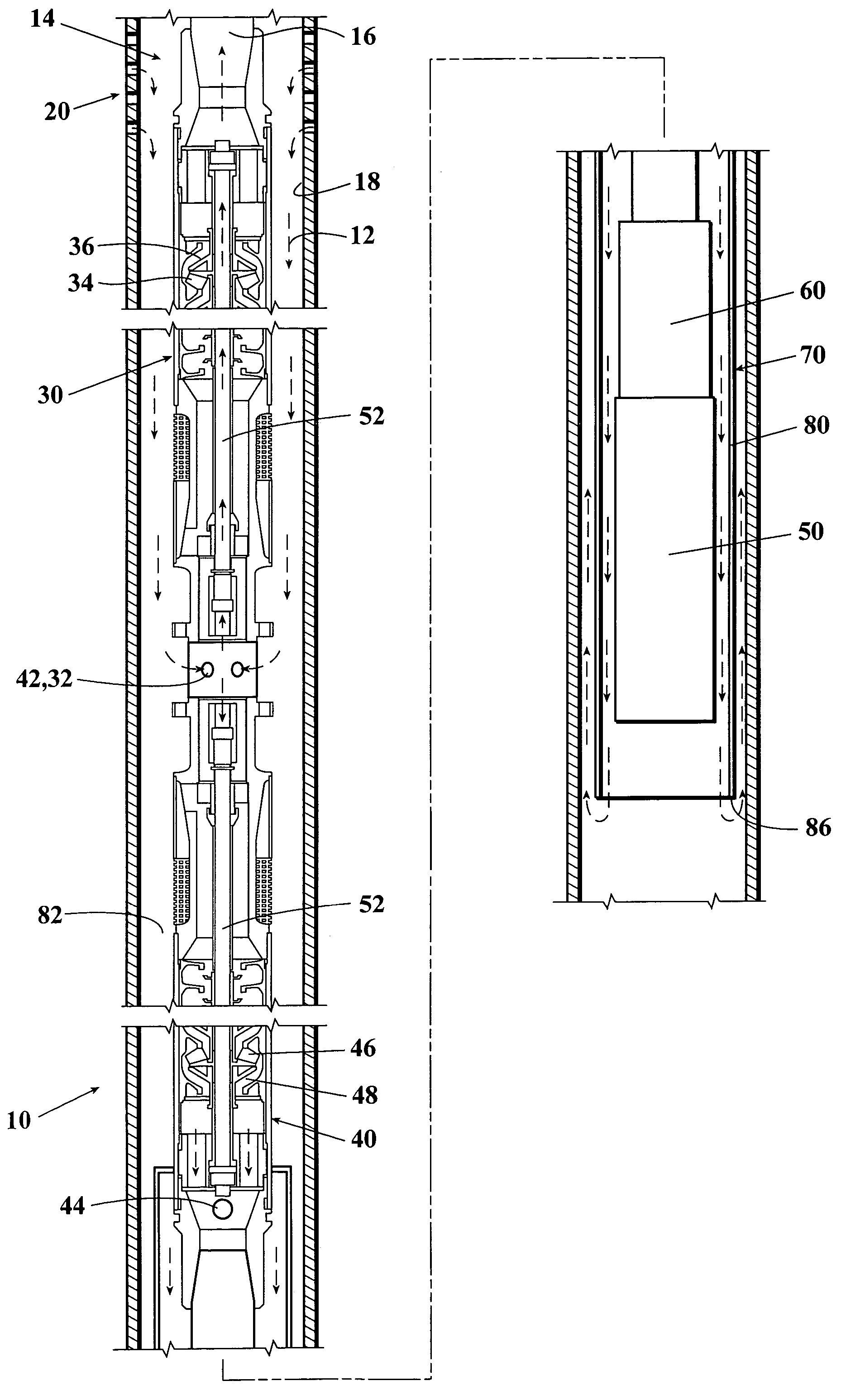
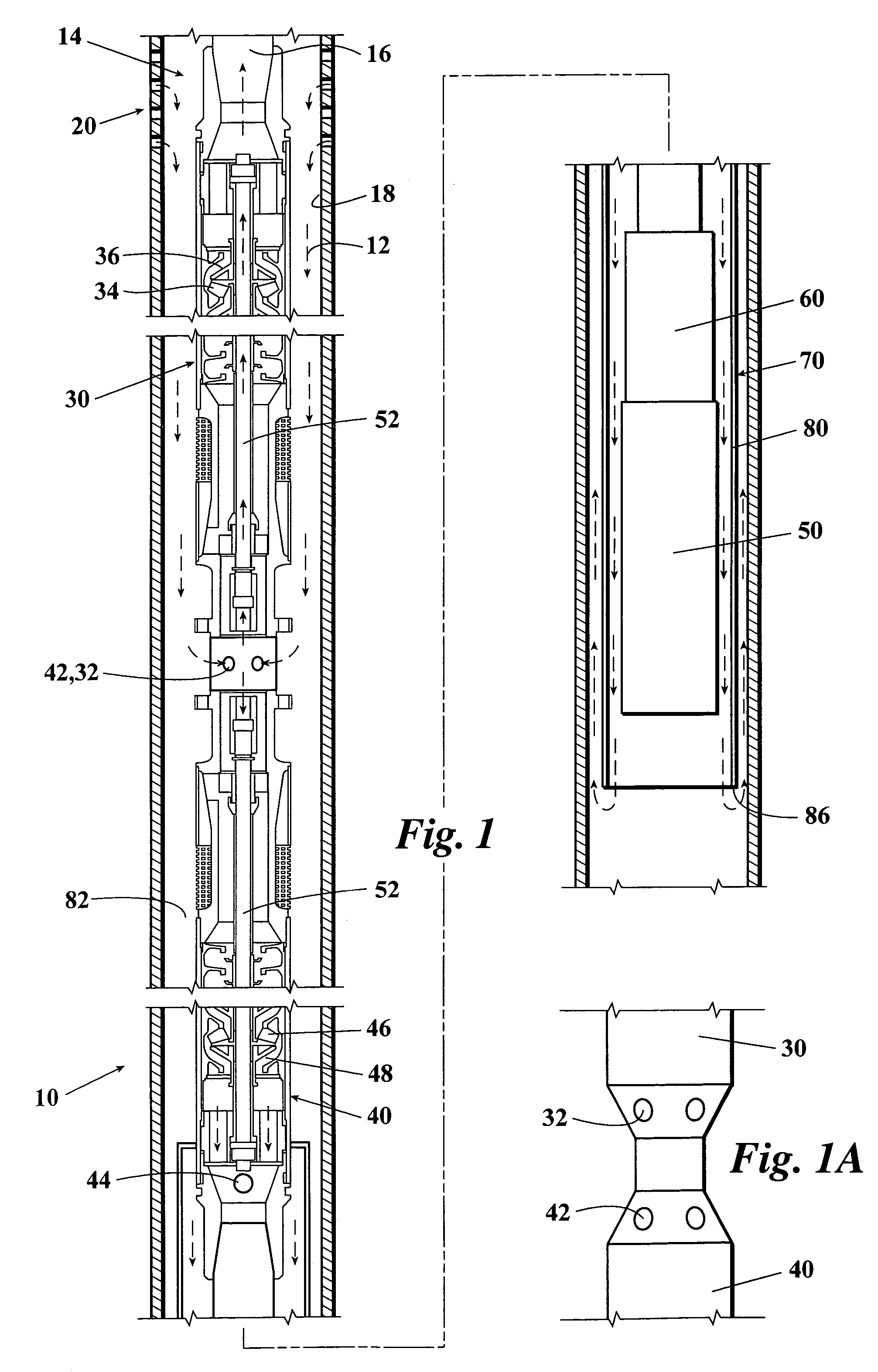
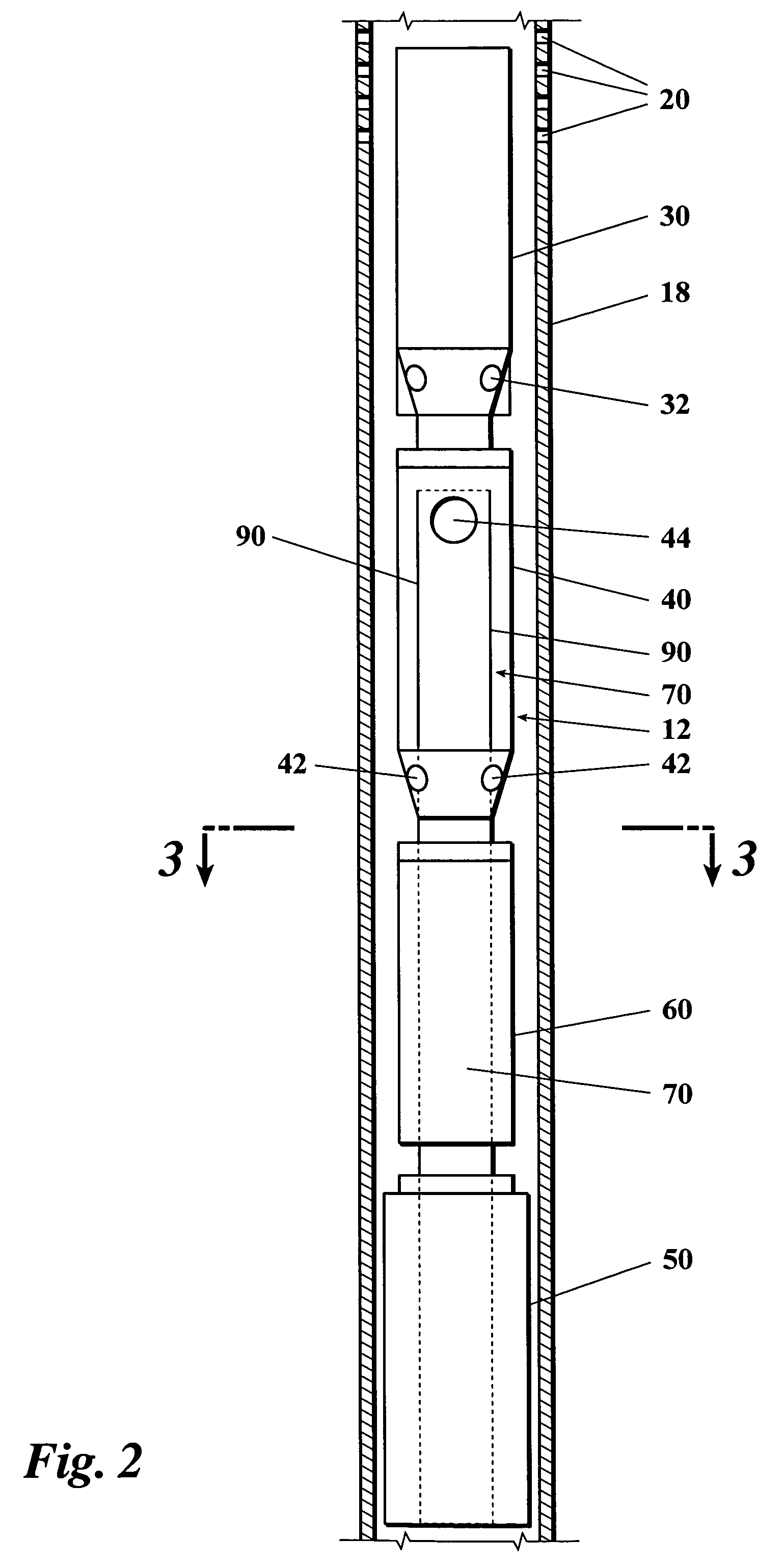
[0014]Referring now to FIGS. 1–4, shown is a motor cooler system 10 for use with an electrical submersible pump (ESP) 12. As shown in FIGS. 1 and 2, an electrical submersible pumping unit 12 is typically suspended on production tubing 16 inside of casing 18 below a well inlet, such as casing perforations 20.

[0015]Electrical submersible pumping unit 12 includes a production pump 30 for directing well fluid upwardly through production tubing 16. Production pump 30 has an intake 32 for receiving well fluids. Production pump 30 may be made up of one or more stages. Each stage includes a plurality of impellers 34 and diffusers 36 (FIG. 1), which are oriented to generate an upward flow of fluid.

[0016]Electrical submersible pumping unit 12 additionally includes a motor cooler pump 40 which is preferably set below production pump 30. Motor cooler pump 40 is provided for directing motor cooling fluid flow downwardly. Motor cooler pump 40 has a motor cooler intake port 42 for receiving well f...


PUM


Abstract

A motor cooler for an electrical submersible pump (ESP). The ESP is typically deployed within casing and defines an annular space between the ESP and the casing. The ESP includes a pump having an intake, a motor cooler pump having an output port, a seal section below the motor cooler pump, and a motor located below a well inlet. Fluid is directed downwardly from the motor cooler pump output port to cool the motor. In one example, a shroud directs fluid received from the motor cooler pump output port downwardly past the motor and back up an outside of the shroud. In another example, longitudinal ribs direct flow in an annular space between the ESP and the casing. Fluid from the motor cooler pump output port is directed downwardly between adjacent ribs over a surface of the motor and then back up between another pair of ribs.

Description

FIELD OF THE INVENTION[0001]The present invention relates to submersible pumps, in more particular the invention relates to an electrical submersible pump employing a flow diverter to direct fluid past the pump motor for cooling.BACKGROUND OF THE INVENTION[0002]Fluid in many producing wells is elevated to the surface by the action of a pumping unit or pumping apparatus installed in the lower portion of the well bore. In recent times there has been increased activity in the drilling of well bores to great depths. The use of water flooding as a means of secondary recovery of oil or other hydrocarbon fluids, after the production thereof has been somewhat depleted, is commonly practiced. Because water flooding produces a considerable quantity of fluid in the producing well bore it is preferable to provide a downhole pumping system capable of producing large quantities of fluid. Electrical submersible pump (ESP) systems have been found to meet this need. The electric motor that is typica...

Claims


Application Information

Patent Timeline
Patent Type & Authority Patents(United States)
IPC IPC(8): E21B43/00
CPCE21B43/128
Inventor BULLOCK, AARON DUANEKNOX, DICK L.
Owner BAKER HUGHES INC
Why Eureka
Try Eureka