
Apparatus and method for resonant-vibratory mixing

a vibrating mixer and vibrating technology, applied in the field of vibrating mixers, can solve the problems of increasing the risk of mechanical damage to cells, limiting the ability of reducing the acceleration of the first mass, and reducing the acceleration of the oscillator. , to achieve the effect of reducing the acceleration of the oscillator, increasing the bearing life, and prolonging the useful life of the components of the devi

Active Publication Date: 2007-03-13
RESODYN ACOUSTIC MIXERS
View PDF21 Cites 155 Cited by
  • Summary
  • Abstract
  • Description
  • Claims
  • Application Information

AI Technical Summary

Benefits of technology

[0025]The present invention provides an apparatus and method for mixing materials, which apparatus and method afford exquisite control over mixing in a wide range of applications. The range of applications extends from heavy-duty agitation for preparation of concrete to delicate and precise mixing required for the preparation of pharmaceuticals and the processing of biological cultures in which living organisms must remain viable through the mixing process. In a preferred embodiment, the present invention provides a vibration mixer, driven by an electronically controllable motor or motors, adapted so as to allow virtually unlimited control of the mixing process.
[0040]In yet another preferred embodiment, the invention is a method of mixing comprising: cyclically imposing a first force on a first movable mass in a first linear direction or a second force on said first movable mass in an opposite linear direction relative to a base, said first movable mass being moved in said first linear direction and then in said opposite linear direction; the movement of said first movable mass causing movement of a second movable mass, said second movable mass being movable in the same directions as said first movable mass and being movably connected to said first movable mass by a first resilient means and being movably connected to said base by a second resilient means; the movement of said first movable mass or said second movable mass causing the movement of a third movable mass, said third movable mass being movable in the same directions as said first movable mass and being movably connected to said second movable mass by a third resilient means and movably connected to said base by a fourth resilient means; the movement of said second movable mass or said third movable mass causing mixing of a composition moved by the movement of said second movable mass or said third movable mass. Preferably, the second movable mass or the third movable mass vibrates at the third harmonic and is operative to produce a force canceling effect, thereby reducing or eliminating forces transmitted to the surrounding environment and increasing mixing efficiency.

Problems solved by technology

Under the turbulent vortex conditions, the cells are at greater risk of being mechanically damaged and the continuous supply of oxygen to the cells is not consistently assured.
This mechanism can be effectively tuned by proper resilient member selections to substantially reduce transmitted forces to the ground position but is limited in its ability to reduce accelerations imposed on the first mass.
Accelerations on the first mass, which includes the driver inducing the cyclical forces, induce high forces which in turn lead to premature failures.
Both cases limit the available applications of the device.
This further limit the device's effectiveness due to the additional power required to operate in this range for optimum mixing accelerations and amplitudes.
The desclosed device lacks the ability to operate at the natural frequency peaks and also suffers from a lack of ability to limit transmitted forces to either the driver or ground positions.
It is not possible to achieve high payload accelerations, force cancellation and low driver accelerations with a two-mass system.
High driver accelerations are an unavoidable result of such a device.

Method used


Image

  • Apparatus and method for resonant-vibratory mixing
  • Apparatus and method for resonant-vibratory mixing
  • Apparatus and method for resonant-vibratory mixing

Examples


Embodiment Construction

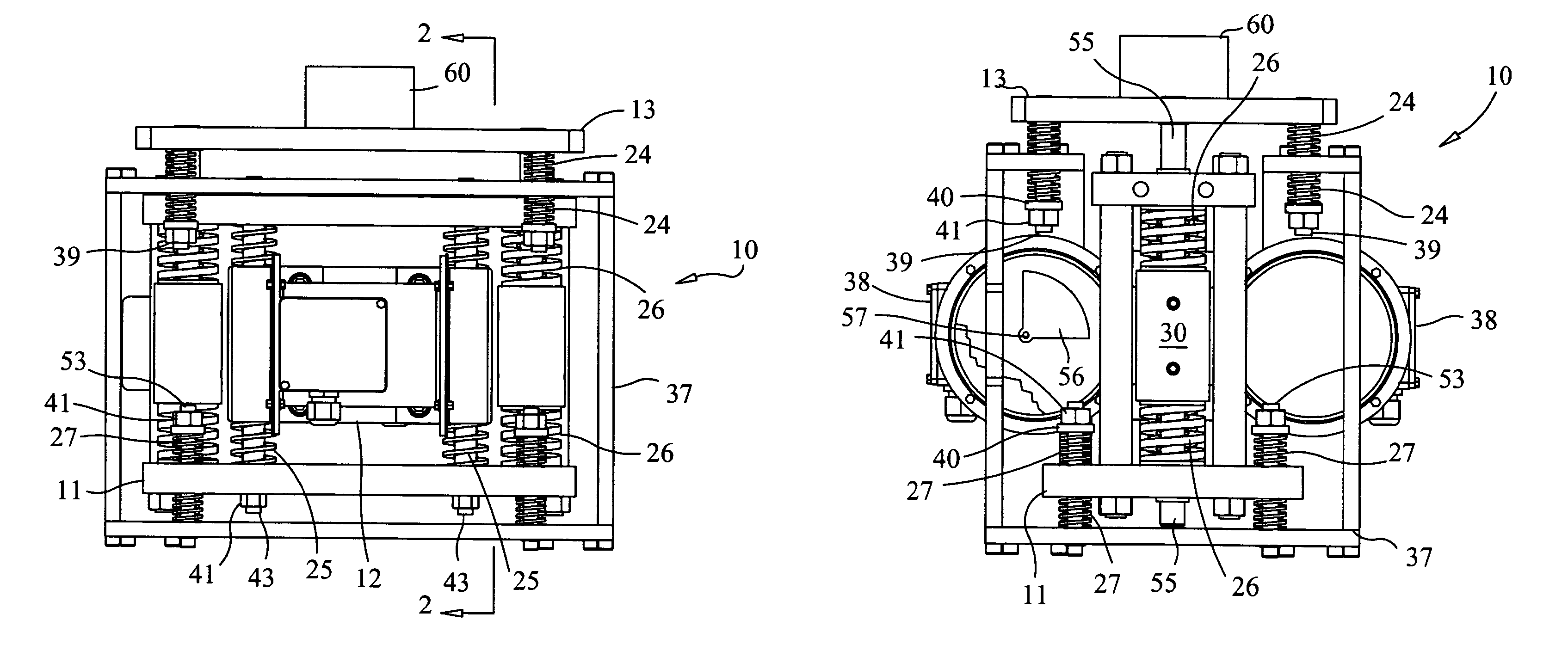
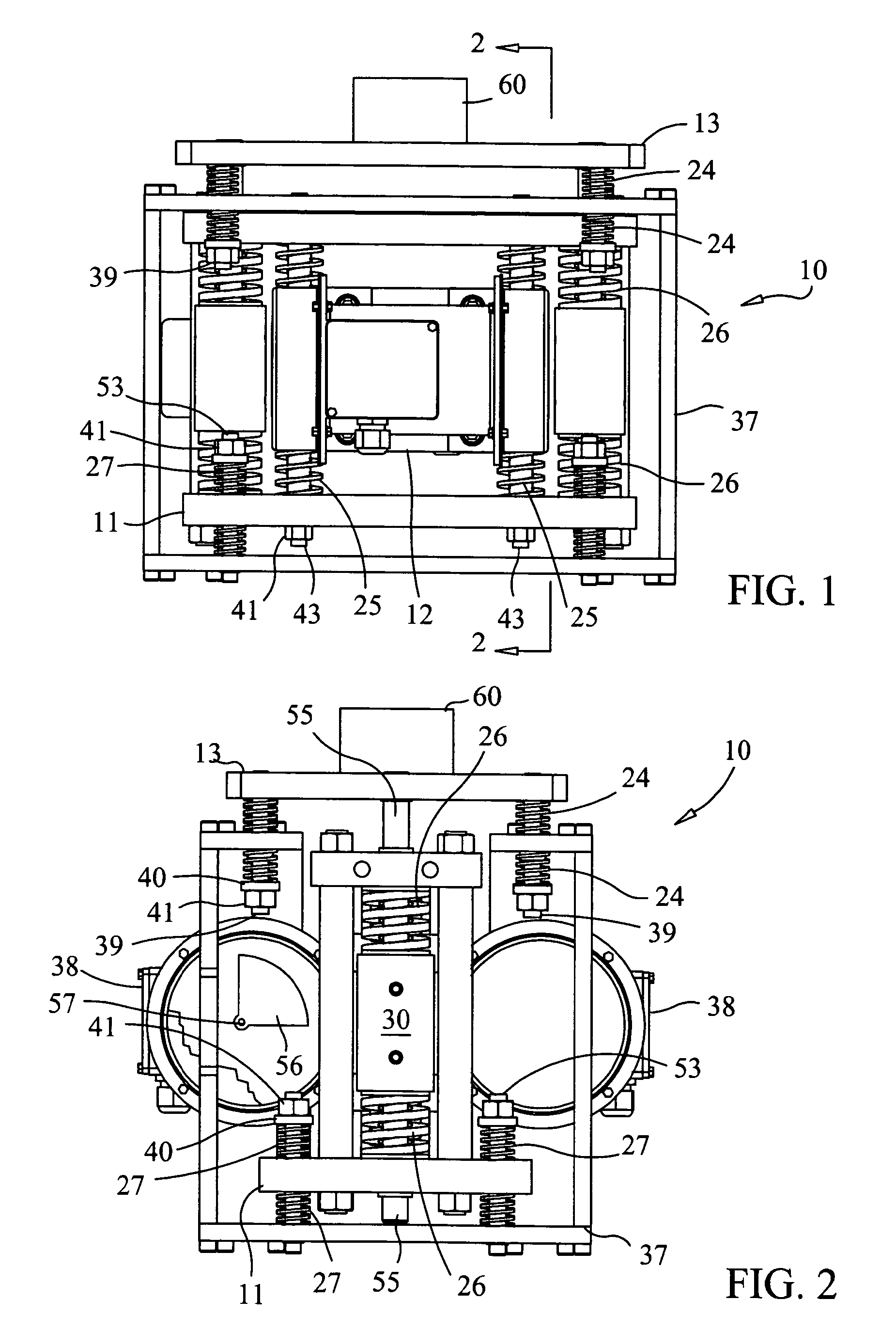
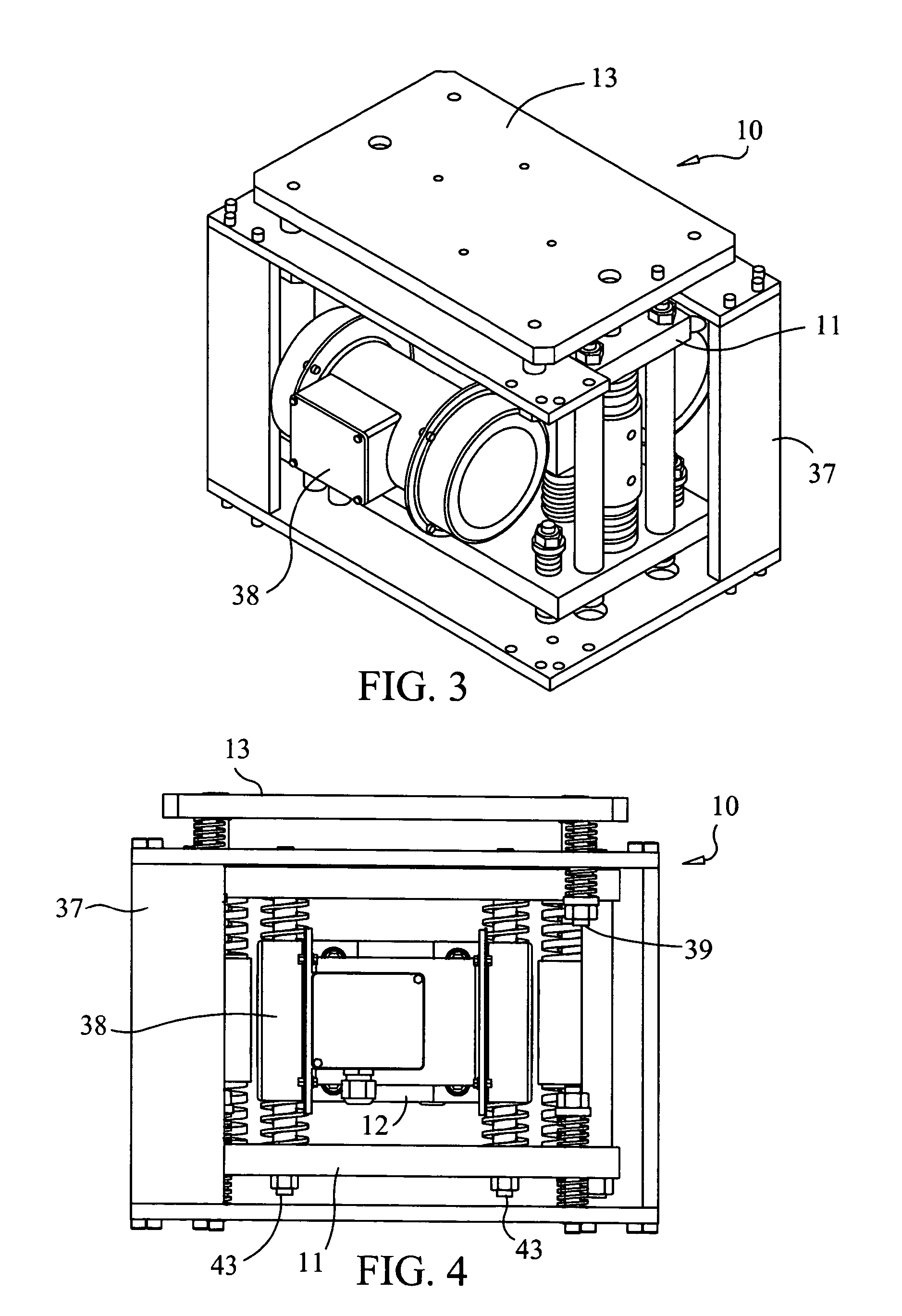
[0129]Referring to FIGS. 1–4, a preferred embodiment of the present invention is presented. Device 10 comprises three independent movable masses (intermediate mass 11, oscillator mass 12 and payload 13) and four distinct spring beds or spring systems (payload mass to ground springs 24, oscillator to intermediate mass springs 25, intermediate mass to payload springs 26 and intermediate mass to ground springs 27) that are housed in rigid structure 7. Oscillator mass 12 is preferably situated between the other two masses. Intermediate mass 11 is preferably situated below oscillator mass 12. Payload 13 is preferably situated above oscillator mass 12. Preferably, all of the masses are constructed of steel or some comparable alloy.

[0130]Oscillator mass 12 is rigidly connected to two oscillator drives 38 (e.g., two direct current (DC) servo motors) and is movably connected to intermediate mass 11 by means of oscillator to intermediate mass alignment struts 43 (two of them that are preferab...


PUM


Abstract

An apparatus and method for mixing fluids and / or solids in a manner that can be varied from maintaining the integrity of fragile molecular and biological materials in the mixing vessel to homogenizing heavy aggregate material by supplying large amounts of energy. Variation in the manner of mixing is accomplished using an electronic controller to generate signals to control the frequency and amplitude of the motor(s), which drive an unbalanced shaft assembly to produce a linear vibratory motion. The motor may be a stepper motors a linear motor or a DC continuous motor. By placing a sensor on the mixing vessel platform to provide feedback control of the mixing motor, the characteristics of agitation in the fluid or solid can be adjusted to optimize the degree of mixing and produce a high quality mixant.

Description

CROSS-REFERENCE TO RELATED APPLICATIONS[0001]This application claims the benefit of U.S. Provisional Application No. 60 / 443,051, filed Jan. 27, 2003, the disclosure of which application is incorporated by reference as if fully set forth herein.STATEMENT REGARDING FEDERALLY SPONSORED RESEARCH OR DEVELOPMENT[0002]The U.S. Government has a paid-up license in this invention and the right in limited circumstances to require the patent owner to license others on reasonable terms as provided for by the terms of Contract No. DAAH01-00-C-R086 awarded by U.S. Army.BACKGROUND OF THE INVENTION[0003]This invention relates generally to mixing and mass transport. In particular, the invention relates to an apparatus and method for resonant-vibratory mixing.[0004]The mixing of fluids involves the creation of fluid motion or agitation resulting in the uniform distribution of either heterogeneous or homogeneous starting materials to form an output product. Mixing processes are called upon to effect th...

Claims


Application Information

Patent Timeline
Patent Type & Authority Patents(United States)
IPC IPC(8): B01F11/00
CPCB06B1/161B01F11/0031B01F31/265
Inventor HOWE, HAROLD WWARRINER, JEREMIAH JCOOK, AARON MCOGUILL, SCOTT LFARRAR, LAWRENCE C
Owner RESODYN ACOUSTIC MIXERS
Learn More