Multi-path cooling of a turbo-generator rotor winding

Active Publication Date: 2007-03-13
GENERAL ELECTRIC TECH GMBH
View PDF17 Cites 10 Cited by
  • Summary
  • Abstract
  • Description
  • Claims
  • Application Information

AI Technical Summary

Benefits of technology

[0019]Optionally the axial ducts are enlarged where necessary to

Problems solved by technology

All of the known cooling schemes described above have draw backs and insufficiencies.
This reversal

Method used


Image

  • Multi-path cooling of a turbo-generator rotor winding
  • Multi-path cooling of a turbo-generator rotor winding
  • Multi-path cooling of a turbo-generator rotor winding

Examples


Embodiment Construction

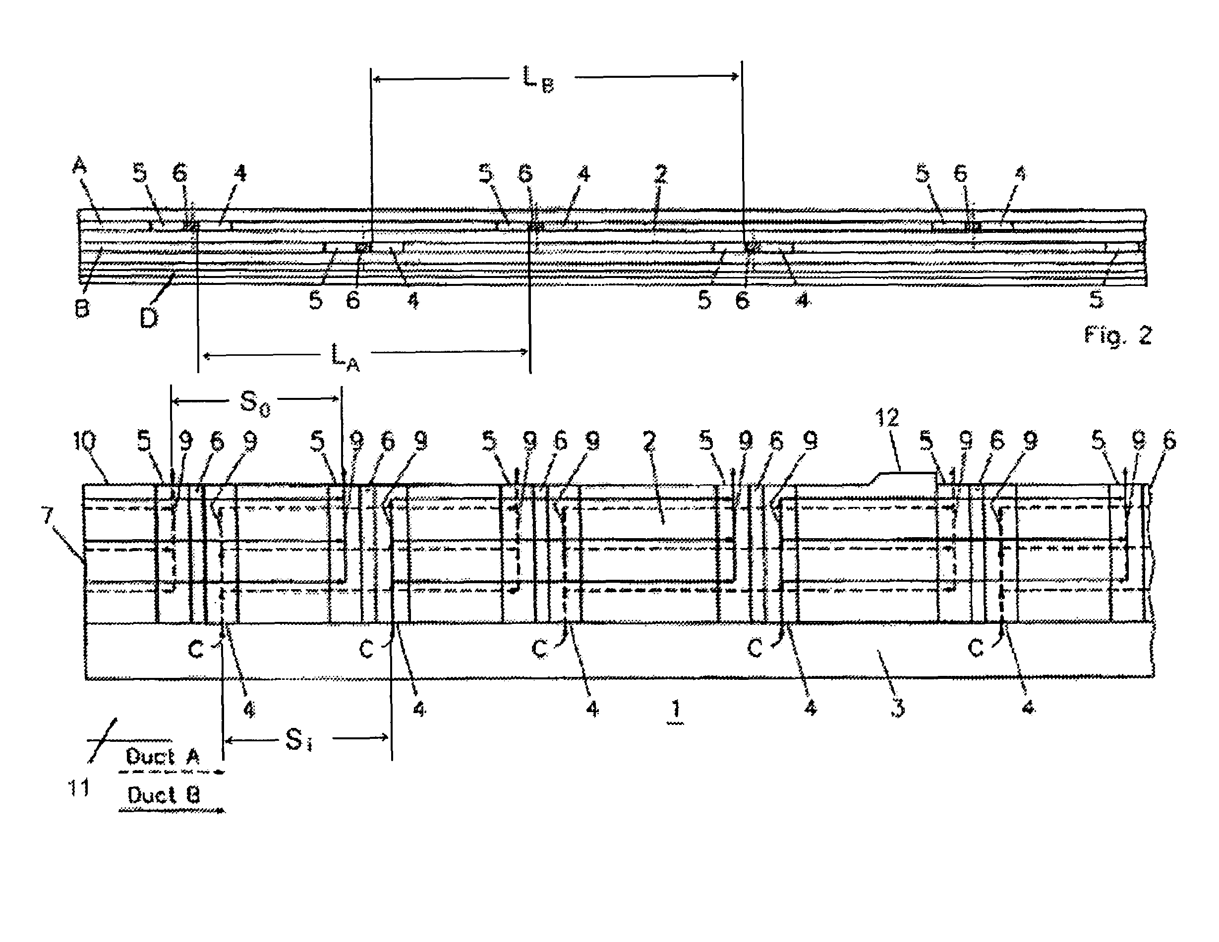
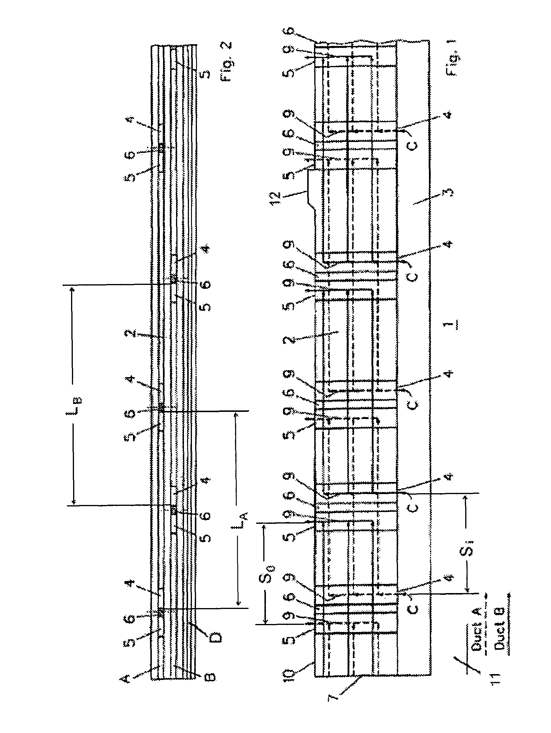
[0027]Referring now to the drawings, wherein like reference numerals designate identical or corresponding parts throughout the several views, a first preferred exemplary embodiment of the invention is reproduced in FIG. 1 in a schematic longitudinal section of one half of a rotor 1.

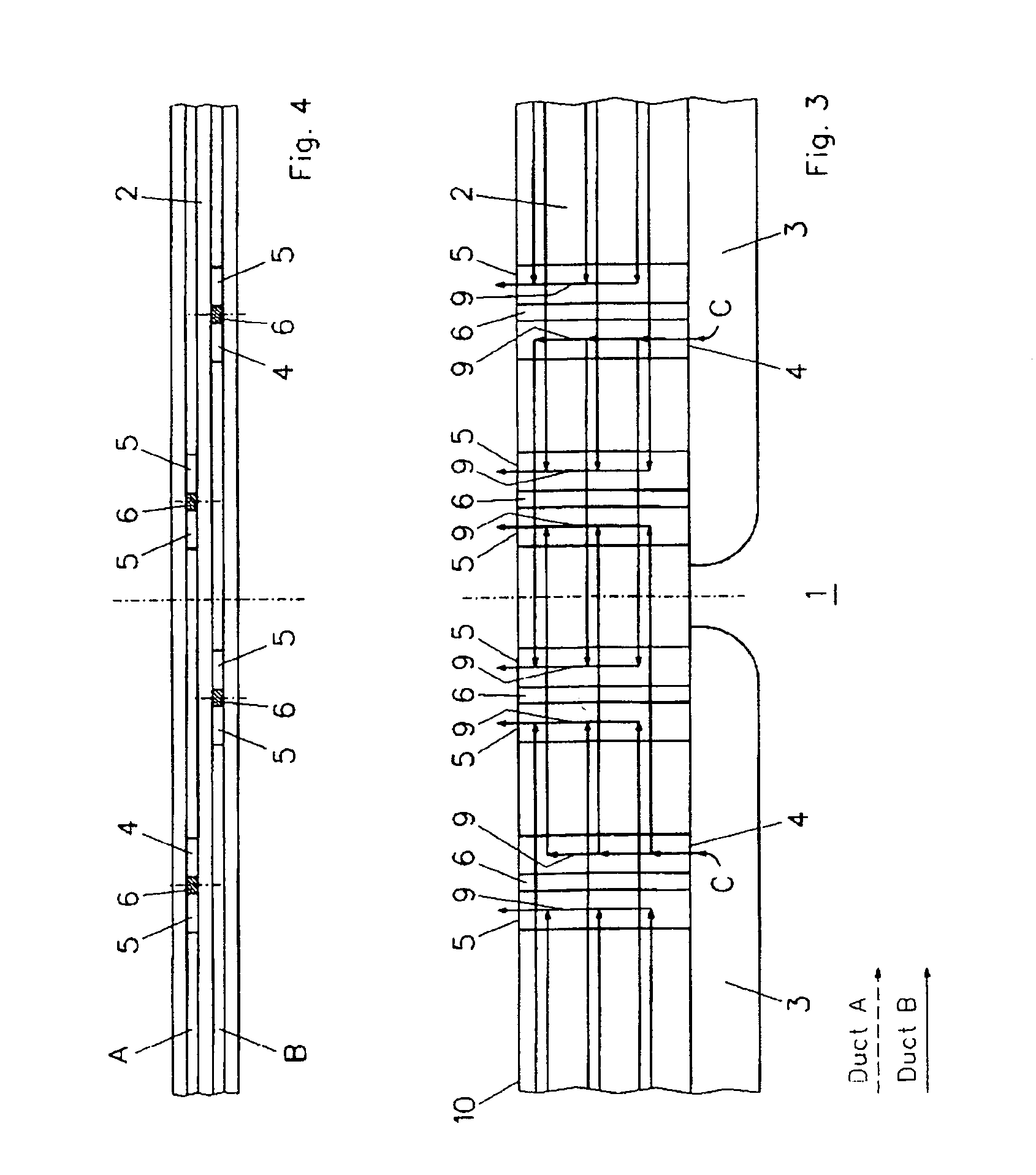
[0028]The upper portion is representing the rotor winding 2 made of E-section or tubular copper as conductor and the lower elongated channel is representing the sub slot 3 for feeding coolant C to the winding 2. The sub slot 3 is arranged between a shaft of the, rotor and the winding 2. In the drawing of FIG. 1, the left edge represents the rotor body end 7.

[0029]In FIG. 1 the axial cooling ducts A are represented by dashed lines and the axial cooling ducts B are represented by solid lines. The axial cooling ducts A and B, having lengths LA and LB, respectively (see FIG, 2), are provided as twin ducts for unidirectional multi path cooling.

[0030]The axial ducts A and B are respectively connected through ra...


PUM


Abstract

A turbo-generator includes a rotor body and a rotor winding disposed around the rotor body. The rotor winding including a sub slot, a first axial cooling duct having a first inlet and a first outlet, and a second axial cooling duct disposed adjacent and parallel to the first axial cooling duct for multi-path cooling. The second axial cooling duct has a second inlet and a second outlet. The first inlet is disposed offset from the second inlet and the first outlet is disposed offset from the second outlet.

Description

[0001]Priority is claimed to United Kingdom Patent Application No. GB 0305300.6, filed on Mar. 7, 2003, the entire disclosure of which is incorporated by reference herein.[0002]The present invention relates generally to the field of dynamo electric machines, and particularly to a turbo-generator having a rotor and a stator concentrically surrounding the rotor and separated from the rotor by an air gap, and having a cooling arrangement with cooling fluid flowing through corresponding cooling passages in the rotor.BACKGROUND[0003]To ensure trouble-free operation and to utilize the full output potential of a turbo generator, large generators must be cooled in order to dissipate the heat loss which occurs in the windings and cores of the rotor and stator. A fluid such as air or even hydrogen is generally used for the cooling and is fed through corresponding bores or slits in the rotor and stator and then cooled down again in a cooler.[0004]In the rotor, the cooling medium flows axially ...

Claims


Application Information

Patent Timeline
IPC IPC(8): H02K1/32H02K3/24H02K9/00
CPCH02K3/24H02K9/005H02K1/32H02K9/00
Inventor MAYOR, KEVIN
Owner GENERAL ELECTRIC TECH GMBH
Why Eureka
Try Eureka