Inductive angle-of-rotation sensor and rotary transducer equipped with the same

a technology of inductive angle rotation and rotary transducer, which is applied in the direction of converting sensor output, coils, using electrical/magnetic means, etc., can solve the problems of intolerant offset error and receipt of printed conductors, and achieve the effect of reducing amplitude errors or differences

Active Publication Date: 2007-03-13
DR JOHANNES HEIDENHAIN GMBH
View PDF12 Cites 12 Cited by
  • Summary
  • Abstract
  • Description
  • Claims
  • Application Information

AI Technical Summary

Benefits of technology

[0008]In accordance with an example embodiment of the present invention, at least one receiving printed conductor on one printed-circuit board supplies an uneven number of signal periods within one rotation relatively to the graduation element, this receiving printed conductor having a first and a second partial section. These partial sections extend in different planes, the first partial section being greater in length than the second. This may make it possible for the offset error of the corresponding signals to be significantly reduced.
[0011]A plurality of such receiving printed conductors may be applied to the printed-circuit board. In an example embodiment of the present invention, each of the longer partial sections may be situated in one and the same plane. This type of construction may minimize amplitude errors or differences in the amplitude of the signals of the individual receiving printed conductors, because the longer partial sections are then each spaced equidistantly from the graduation element.

Problems solved by technology

When reducing the size of such an angle-of-rotation sensor, particularly when reducing the diameter of the scanning circuit board, it becomes evident that the receiving printed conductors, in particular, which supply signals having one signal period over one rotation, produce an intolerable offset error.

Method used


Image

  • Inductive angle-of-rotation sensor and rotary transducer equipped with the same
  • Inductive angle-of-rotation sensor and rotary transducer equipped with the same
  • Inductive angle-of-rotation sensor and rotary transducer equipped with the same

Examples


Embodiment Construction

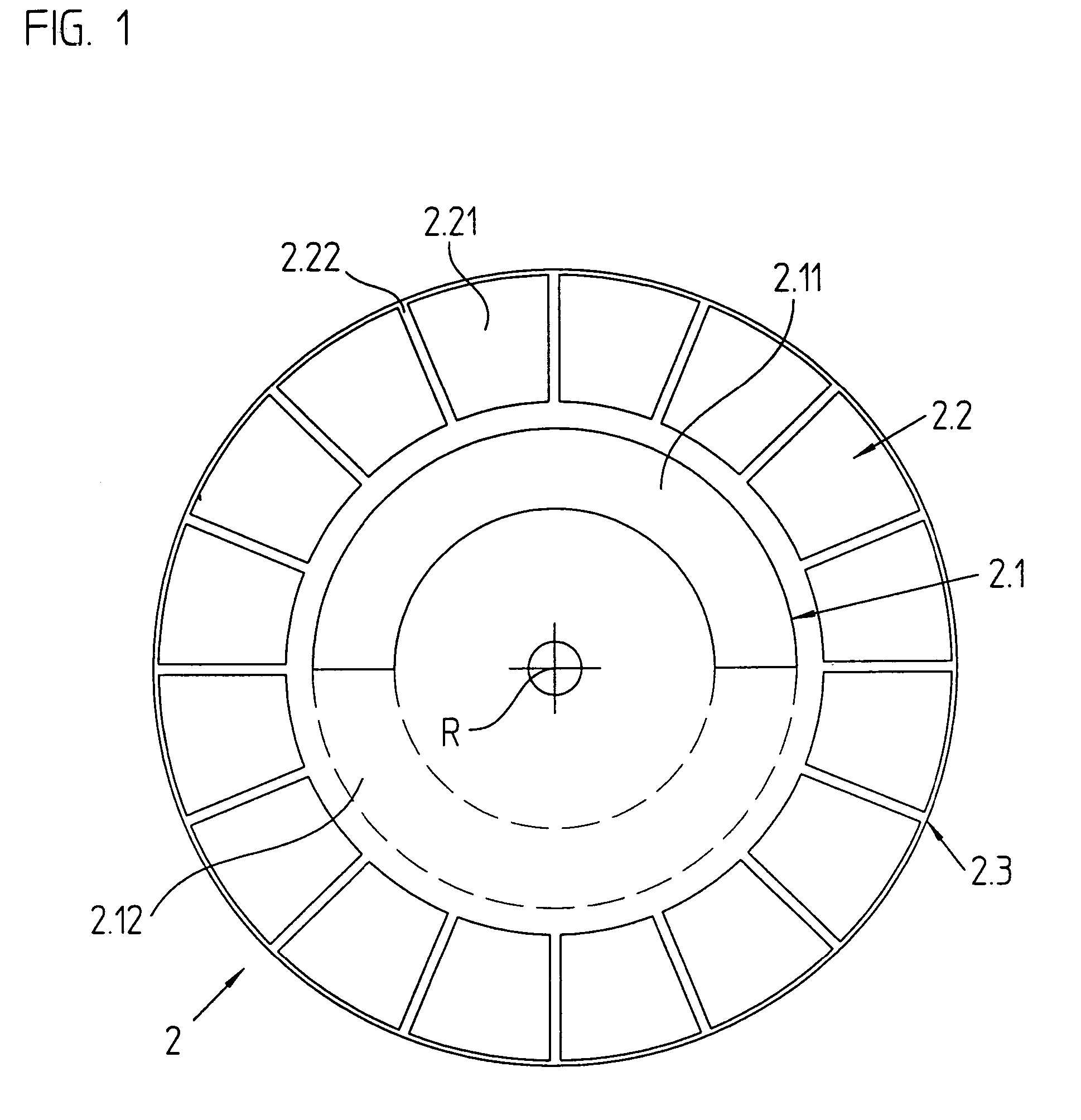
[0027]The basic design of an angle-of-rotation sensor in accordance with an example embodiment of the present invention is illustrated in FIGS. 1 to 3. FIG. 1 shows a graduation element in the form of a circular graduated disk 2. Graduated disk 2 is made up of a substrate 2.3, which, in the illustrated exemplary embodiment, is fabricated from epoxy resin, and on which two graduation or graduation tracks 2.1, 2.2 are arranged. Graduation tracks 2.1, 2.2 have a circular form and are concentrically arranged, with respect to an axis of rotation R, with different diameters on substrate 2.3. The two graduation tracks 2.1, 2.2 are each composed of a regular sequence of alternately arranged electrically conductive graduation regions 2.11, 2.21 and non-conductive graduation regions 2.12, 2.22. As material for electrically conductive graduation regions 2.11, 2.21 in the illustrated example, copper is applied to substrate 2.3. On the other hand, substrate 2.3 is not coated in non-conductive gr...


PUM

PropertyMeasurementUnit
widthaaaaaaaaaa
widthaaaaaaaaaa
angleaaaaaaaaaa

Abstract

An inductive angle-of-rotation sensor, which is composed of a printed-circuit board, on which an excitation printed conductor and a receiving printed conductor are applied, the receiving printed conductor having a first partial section, which extends in a first plane, and a second partial section, which runs in a second plane. In addition, the inductive angle-of-rotation sensor has a graduation element, which is rotatable in relation to the printed-circuit board and includes a graduation track, which is composed of alternately arranged, electrically conductive and non-conductive graduation regions. The receiving printed conductor supplies an uneven number of signal periods within one rotation relatively to the graduation element. The first partial section of the receiving printed conductor is substantially greater in length than the second partial section. Moreover, a rotary transducer may be equipped with this angle-of-rotation sensor.

Description

CROSS-REFERENCE TO RELATED APPLICATIONS[0001]The present application claims priority to application Ser. No. 103 20 990.5, filed in the Federal Republic of Germany on May 9, 2003, which is expressly incorporated herein in its entirety by reference thereto.FIELD OF THE INVENTION[0002]The present invention relates to an inductive angle-of-rotation sensor for determining relative angular positions and to a rotary or position transducer equipped with the same.BACKGROUND INFORMATION[0003]Inductive angle-of-rotation sensors are used, for example, in rotary transducers to determine the angular position of two machine parts that are rotatable relatively to one another. In inductive angle-of-rotation sensors, excitation coils and receiving coils, for instance, in the form of printed conductors, are applied to a shared printed-circuit board, which is permanently connected, for example, to a stator of a rotary transducer. Disposed oppositely to this printed-circuit board is another board, e.g....

Claims


Application Information

Patent Timeline
Patent Type & Authority Patents(United States)
IPC IPC(8): G01B7/30G01R33/02H01F5/04G01D5/245G01D5/20
CPCG01D5/2053
Inventor TIEMANN, MARC OLIVER
Owner DR JOHANNES HEIDENHAIN GMBH
Why Eureka
Try Eureka