Dual-edge synchronized data sampler

a synchronized data and sampler technology, applied in the field of sampler circuits, can solve the problems of increasing difficulty in distributing accurate, jitter-free clocks, and conventional ddr circuits not being able to operate at the high speed required by many modern applications

Active Publication Date: 2007-03-13
XILINX INC
View PDF1 Cites 9 Cited by
  • Summary
  • Abstract
  • Description
  • Claims
  • Application Information

AI Technical Summary

Benefits of technology

[0007]A sampling circuit for sampling an data signal responsive to a clock signal is described. An exemplary embodiment includes a dual-edge sampler having a clock terminal for receiving the clock signal, a data input terminal for receiving the data signal, an output terminal for providing an output signal, and an asynchronous level mode state machine configured to sample the data signal at every edge of the clock signal and provide sampled data as the output signal. In some embodiments, the asynchronous level mode state machine may include one or more differential logic blocks for generating one or more intermediate results responsive to current state information and the data signal. In some embodiments, the sampling circuit may have a toggle function. In some embodiments the sampling circuit may include edge control logic for selectively configuring the sampler as a rising edge or falling edge triggered sampler responsive to an edge control signal.

Problems solved by technology

One of the critical challenges for circuit designers is managing timing of their designs.
This challenge to manage timing, however, has become greater as circuits grow more complex and clock frequencies increase.
At very high frequencies, distributing an accurate, jitter-free clock becomes increasingly difficult.
Furthermore, conventional DDR circuits may not be capable of operating at the high speeds required by many modern applications.
Also, a conventional DDR circuit can introduce asymmetry or other errors in a design.

Method used


Image

  • Dual-edge synchronized data sampler
  • Dual-edge synchronized data sampler
  • Dual-edge synchronized data sampler

Examples


Embodiment Construction

[0016]The present invention is believed to be applicable to a variety of integrated circuits and designs, including clock management circuits and memory interfaces. While the present invention is not so limited, an appreciation of the present invention is presented by way of specific examples. The specific details are set forth to provide a more thorough understanding of the present invention. However, it will be apparent to one ordinarily skilled in the art that the present invention can be practiced without these specific details. In other instances, well-known circuits and devices may be omitted or presented in abstract form in order to avoid obscuring the present invention.

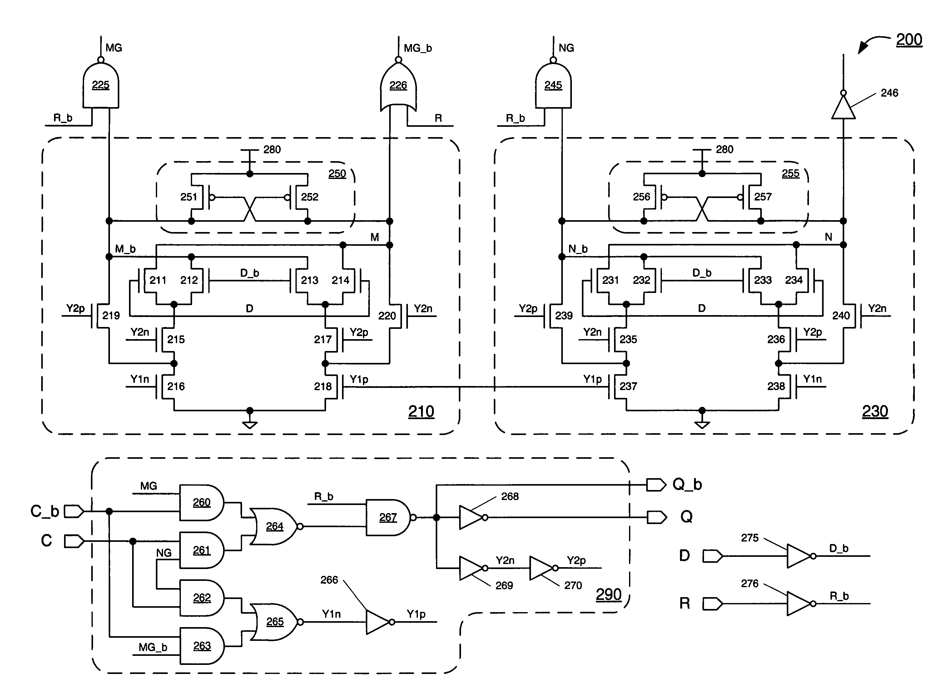
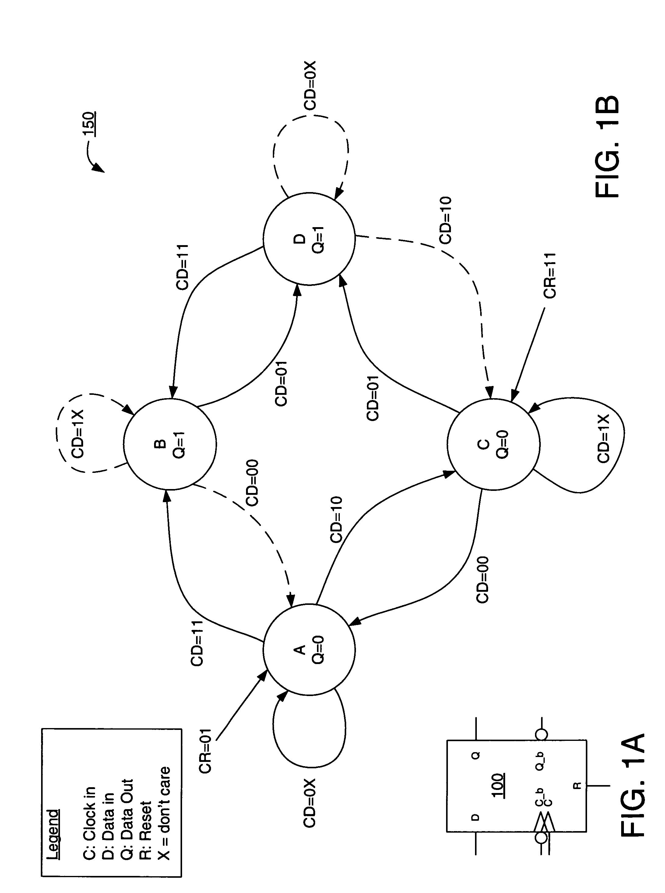
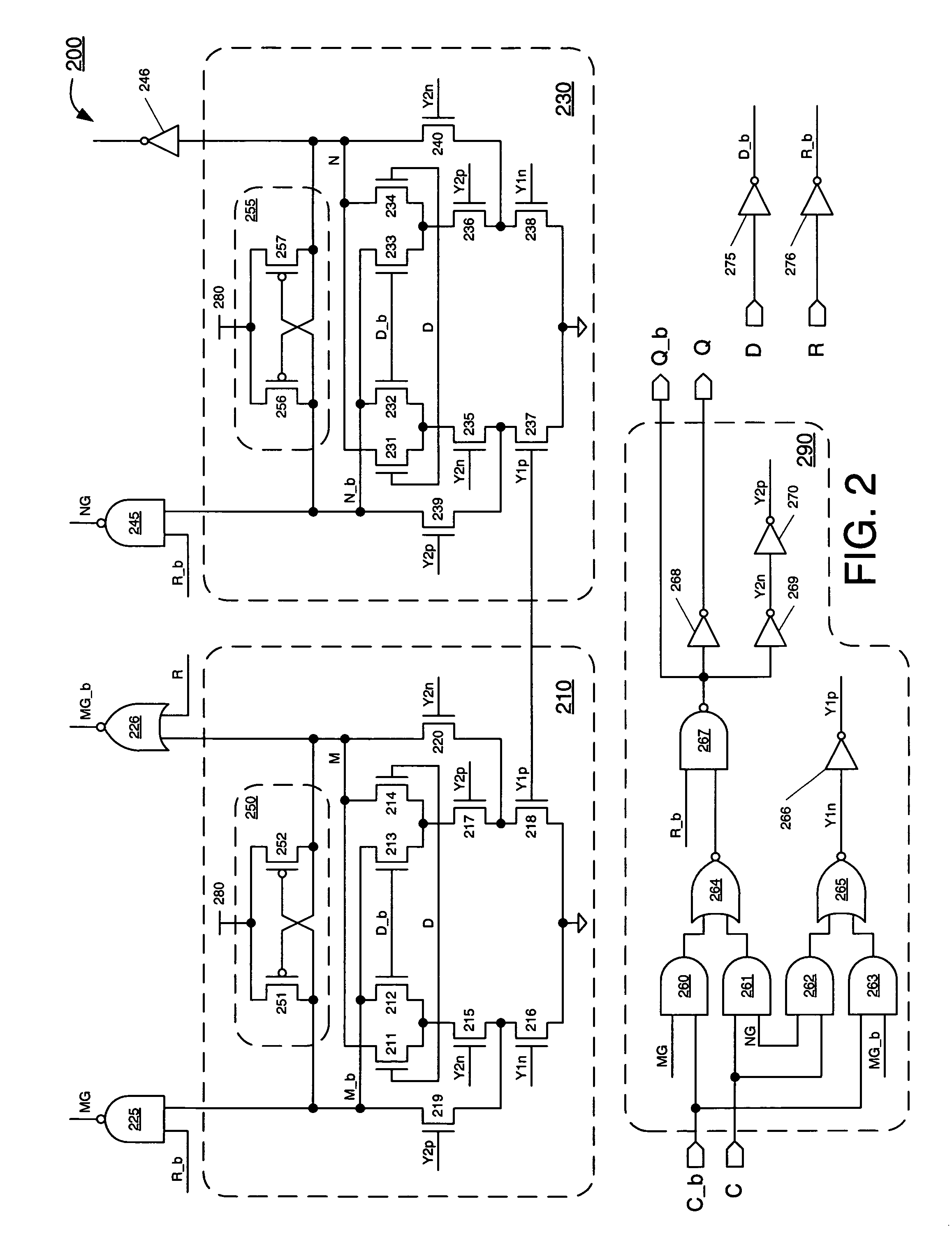
[0017]FIGS. 1A and 1B show a dual edge sampler 100 and a state diagram 150 of the dual-edge sampler in accordance with an embodiment of the present invention. As described in greater detail below, sampler 100 may be implemented as an asynchronous level mode state machine. In some embodiments, part or all of sa...


PUM


Abstract

A dual-edge synchronized sampler having an efficient implementation for high speed and high performance operation is described. The sampler receives a data input signal and a clock input signal and uses an asynchronous level mode state machine to sample the data input signal responsive to level changes in the clock input signal. In some embodiments, the sampler includes at least one differential logic block for implementing the asynchronous level mode state machine. The sampler has symmetric clock-to-Q propagation delays for both rising and falling edges of the clock input signal. The sampler may include toggle functionality, and may include edge control logic for configuring the sampler as one of a rising edge and falling edge sampler.

Description

FIELD OF THE INVENTION[0001]The invention relates to sampler circuits, and more particularly, to a dual-edged synchronized data sampler.BACKGROUND OF THE INVENTION[0002]One of the critical challenges for circuit designers is managing timing of their designs. Precise control over timing and clock signals can enable higher performance and more reliable designs. This challenge to manage timing, however, has become greater as circuits grow more complex and clock frequencies increase.[0003]Dual or double data rate (DDR) applications and designs have become increasingly popular as clock rates continue to increase into the gigahertz range and beyond. At very high frequencies, distributing an accurate, jitter-free clock becomes increasingly difficult. A double data rate application mitigates this problem by using both rising and falling edges of a clock. Thus, a DDR application only requires a clock having half the frequency of the corresponding data rate. DDR interfaces are commonly used f...

Claims


Application Information

Patent Timeline
Patent Type & Authority Patents(United States)
IPC IPC(8): H03L7/00
CPCH03K3/356121G11C27/02H04L7/0087
Inventor KAVIANI, ALIREZA S.
Owner XILINX INC
Why Eureka
Try Eureka