Spatial optical communication apparatus

a technology of optical communication and satellite, applied in the direction of optical elements, satellite communication transmission, instruments, etc., can solve the problems of difficult to achieve stable communication, light beams are liable to deviate from a partner apparatus, and each apparatus, however, has its advantages and disadvantages

Inactive Publication Date: 2007-03-13
CANON KK
View PDF3 Cites 8 Cited by
  • Summary
  • Abstract
  • Description
  • Claims
  • Application Information

AI Technical Summary

Benefits of technology

[0014]It is an object of the present invention to provide a spatial optical communication apparatus that can solve the above-discussed problems.
[0018]In another preferred embodiment, the optical system includes an optical detector for detecting an angular difference between an optical axis of the optical system and reception light from the partner apparatus, the first unit is controlled on the basis of a low frequency component of an angular signal supplied from the optical detector such that the angular difference between the optical axis of the optical system and the reception light from the partner apparatus can be corrected, and the second unit is controlled on the basis of a high frequency component of the angular signal supplied from the optical detector such that the angular difference between the optical axis of the optical system and the reception light from the partner apparatus can be corrected.

Problems solved by technology

However, when the light beam is narrowed, the light beam is liable to deviate from a partner apparatus due to the angular variation caused by vibrations of a building or an installation mount resultant from wind pressure, distortion resultant from temperature fluctuation, or the like.
Stable communication is hence difficult to achieve.
Each apparatus, however, has its advantage and disadvantage.
Specifically, in a system which includes the driving mechanism provided outside the optical system, and changes the angle of the entire optical system as illustrated in FIG. 4, the variable angle range can be freely widened to cope with a wide angular variation, but it is difficult to rapidly change the angle and to respond to a high-speed angular variation since a relatively heavy mechanism needs to be driven.
On the other hand, in a system which includes the light deflection mechanism provided inside the optical system as illustrated in FIG. 6, a high-speed angular variation can be handled since it is relatively easy to rapidly change the angle of light, but it is difficult to increase the variable angle range since the size of the optical system is limited and the light beam is hence likely to deviate from the optical system if the angle is largely changed.

Method used


Image

  • Spatial optical communication apparatus
  • Spatial optical communication apparatus
  • Spatial optical communication apparatus

Examples


first embodiment

[0030](First Embodiment)

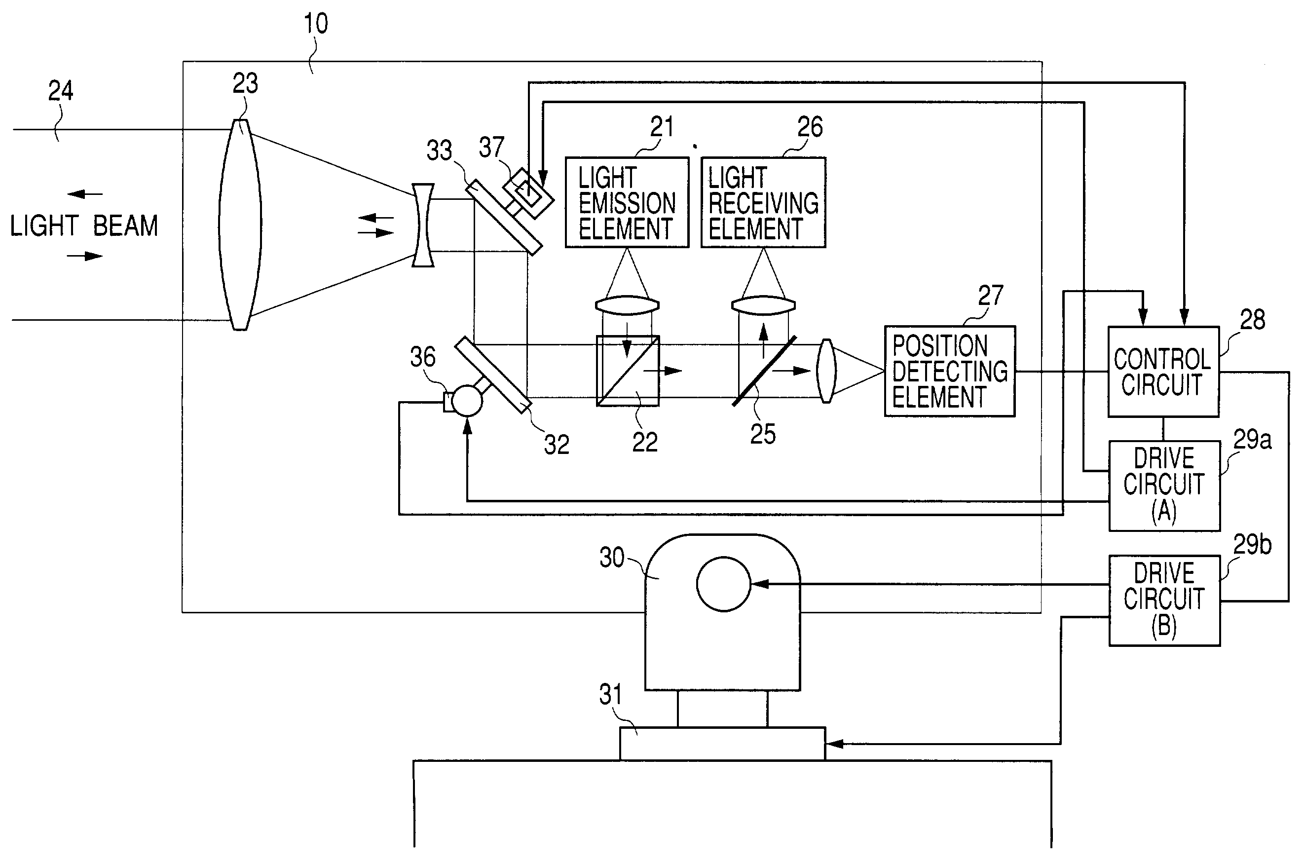
[0031]FIG. 1 shows a spatial optical transmission apparatus having the optical-axis deviation correcting function according to the present invention.

[0032]In FIG. 1, light from a light emission element 21 is reflected toward a light transmission and reception lens 23 by a polarization beam splitter 22, similar to the conventional apparatuses as illustrated in FIG. 4 and FIG. 6. After its direction is correctly adjusted by light deflection mirrors 32 and 33, the reflected light is transmitted toward the direction of a partner apparatus as a substantially parallel light beam 24 with a small divergence.

[0033]Light from the partner apparatus is reversely guided along the same optical axis as that of the transmission optical signal from the subject apparatus, and the light thus passes through the light transmission and reception lens 23, is reflected by the light deflection mirrors 32 and 33, and enters the polarization beam splitter 22. This reception light from ...

second embodiment

[0039](Second Embodiment)

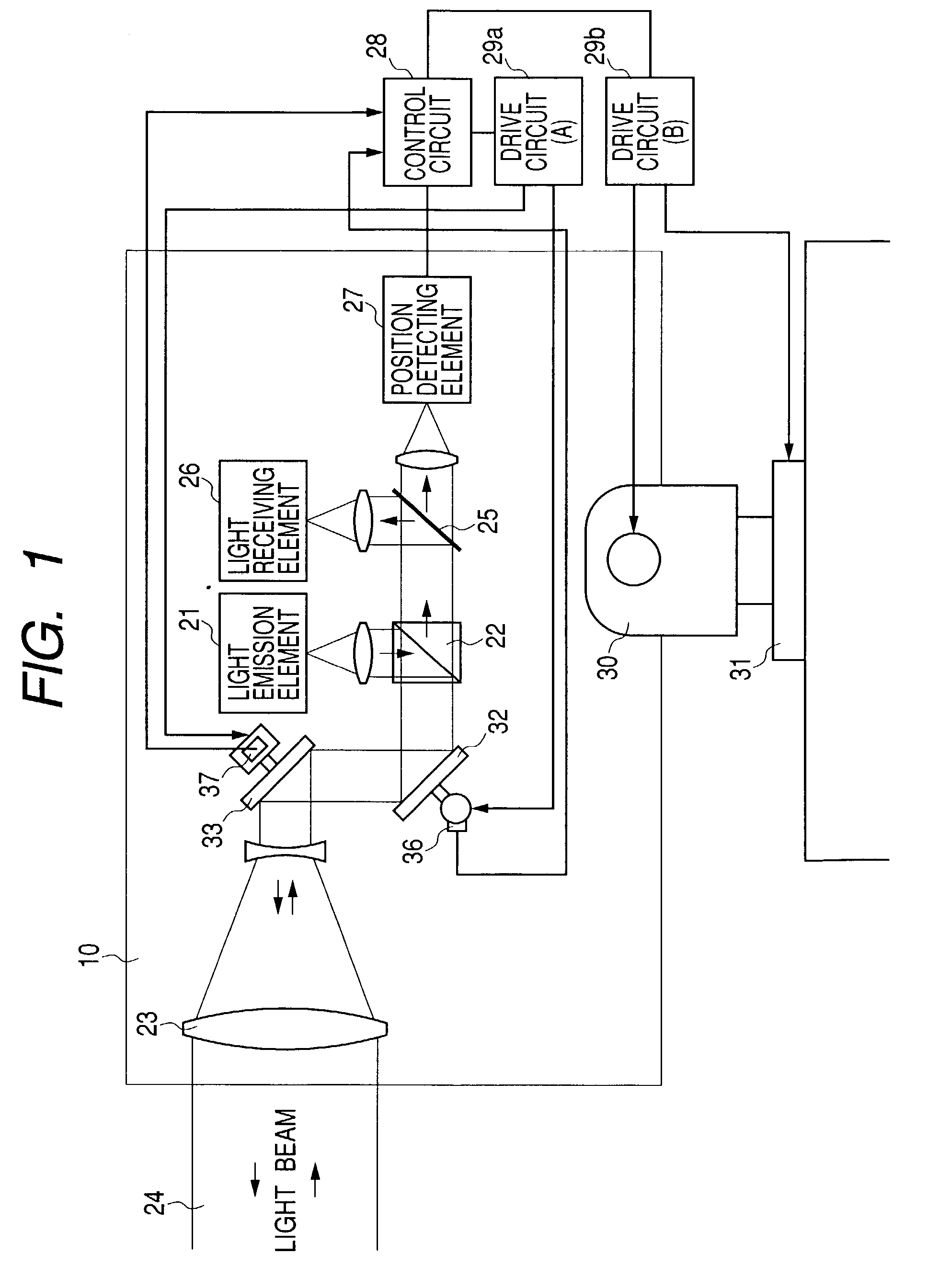
[0040]A second embodiment of FIG. 2 uses a so-called lens shift optical system 38 as a means for deflecting light at high rate in the optical system in place of the light deflection mirrors 32 and 33. A lens of the lens shift optical system 38 is moved perpendicularly to the optical axis. Movement of the lens in the sheet of FIG. 2 is indicated in FIG. 2, but actually the lens can be freely moved in a two-dimensional manner along directions parallel and perpendicular to the sheet of FIG. 2. The light beam 24 is deflected in accordance with the shift amount of the lens. A driving means for the lens shift can be an actuator using a voice coil, a linear motor, or the like.

[0041]The second embodiment further includes a lens position sensor 39 for detecting shift amounts of the lens in the parallel and perpendicular directions. The lens position sensor 39 supplies position information to the control circuit 28, similar to the first embodiment, to control the driv...

third embodiment

[0042](Third Embodiment)

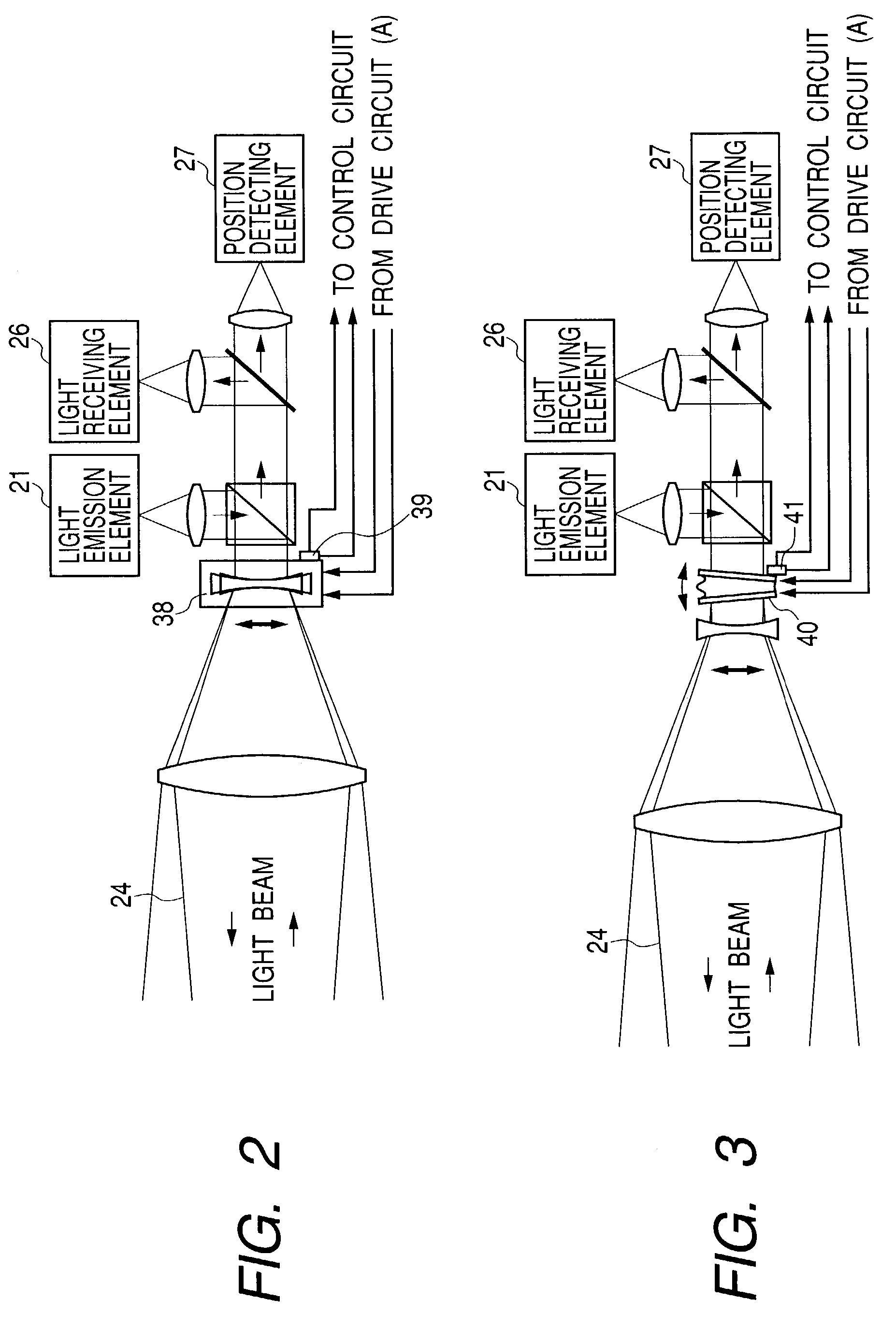
[0043]A third embodiment of FIG. 3 uses a variable vertex-angle prism 40 as a means for deflecting light at high rate in the optical system in place of the light deflection mirrors 32 and 33. In the variable vertex-angle prism 40, transparent liquid is provided between two transparent plates, and the magnitude of the lens effect of light deflection and the like is varied by changing the angle between the two transparent plates. Vertex-angle drive in the sheet of FIG. 3 is indicated in FIG. 3, but actually the vertex angle can be freely changed in a two-dimensional manner along directions parallel and perpendicular to the sheet of FIG. 3. Optical angle of refraction is changed, and the light beam 24 is hence deflected in accordance with the amount of change of the vertex angle. A driving means for varying the vertex angle can be an actuator using a voice coil, a linear motor, or the like, similar to the second embodiment.

[0044]The third embodiment further incl...


PUM


Abstract

In a disclosed spatial optical communication apparatus, the optical-axis deviation correction is possible at the same time for both high-speed angular variation with a small amplitude and low-speed angular variation with a large amplitude, and the apparatus has a function of correcting the optical-axis deviation whose application range is wide and whose correction ability is high. To achieve such function, the spatial optical communication apparatus for performing communication between spaced locations with a light beam is provided with both a light deflecting unit set inside an optical system with a narrow variable angle range and a fast response speed, and an optical system driving unit set outside the optical system with a slow response speed and a wide variable angle range.

Description

BACKGROUND OF THE INVENTION[0001]1. Field of the Invention[0002]The present invention relates to a spatial optical communication apparatus for performing communication by transmitting an optical signal with a light beam through free space between spaced opposed locations, and particularly to an apparatus having a function of correcting the deviation of an optical axis of a light beam due to the angular shift of the apparatus.[0003]2. Related Background Art[0004]In general, with a spatial optical communication apparatus for performing communication by transmitting a light beam through free space, it is necessary to use a narrow light beam whose divergent angle is made as small as possible such that the power of light can be effectively transmitted. However, when the light beam is narrowed, the light beam is liable to deviate from a partner apparatus due to the angular variation caused by vibrations of a building or an installation mount resultant from wind pressure, distortion result...

Claims


Application Information

Patent Timeline
Patent Type & Authority Patents(United States)
IPC IPC(8): H04B10/00G02B26/08G02B5/04G02B7/198H04B10/07H04B10/11
CPCH04B10/118
Inventor SAKANAKA, TETSUO
Owner CANON KK
Why Eureka
Try Eureka