Bow lifting body

a lifting body and bow technology, applied in the field of bows and watercraft, can solve the problems of unadjusted prior art structure, adverse effects, submerged bodies of marine vessels, etc., and achieve the effect of increasing the l/d ratio of the entire system, increasing the payload capacity of the ship, and increasing the lift to drag ratio

Active Publication Date: 2007-03-20
HULL SCI RES LLC
View PDF21 Cites 8 Cited by
  • Summary
  • Abstract
  • Description
  • Claims
  • Application Information

AI Technical Summary

Benefits of technology

[0012]In accordance with an aspect of the present invention, an underwater lifting body is provided that meets these objectives. In particular a lifting body of the general type described in U.S. Pat. No. 6,263,819 is secured to the bow of a watercraft hull below the vessel's design water line for improved efficiency and motions in a seaway. Such bow attached lifting bodies are referred to herein as a Bow Lifting Body or BLB.
[0019]Because lifting bodies have a higher lift to drag ratio (L / D, efficiency) than that of a hull alone, most noticeably at high speeds, by adding a BLB component with a higher L / D ratio than that of the original system without such an addition, it is intuitive that the L / D ratio of the entire system increases.
[0020]In addition, a typical lifting body can lift as much as five (5) times its own displacement at speed. By adding a lifting body at the bow of a ship, this dynamic lift increases the payload capacity of the ship. A BLB with a high L / D ratio can introduce such possibilities as the option to shift the longitudinal center of gravity (LCG) toward the bow of the ship by means of adding fuel, payload, ballast tanks or similar. This shift in LCG can be desirable in certain seaways to reduce pitching motions.
[0021]Furthermore, by the introduction of an underwater body with a large platform area at the bow of a ship, the added mass in the vertical direction is increased, which significantly reduces unwanted motion.
[0022]Moreover, the motions of the ship in a seaway can be additionally reduced if the underwater body has active control surfaces which are linked to an Active Ride Control System (ARCS). A BLB offers the option of either being a passive, or active ride control device.

Problems solved by technology

More specifically, as disclosed in U.S. Pat. No. 6,263,819, it was found that the submerged bodies of marine vessels, when operated at shallow submergence depths, such as is the case for SWAS and Mid-Foil vessels, can be adversely effected by the displacement of the free water surface caused by the body's volume and dynamic flow effects.
The interaction of that displacement of the free surface relative to the body's shape had not been adequately accounted for in the prior art structures.
It is believed that this inadequacy of existing prior art submerged bodies for marine vessels is the result of the fact that submerged and semi-submerged marine vessels have historically been designed to operate at great depths relative to their underwater body thickness, as with submarines or hydrofoils.
The displacement of water at the free surface by a submerged body is detrimental to a marine vessel's hydrodynamic performance with the impact varying as a function of the body's shape, submergence depth, speed and trim.
For example, the free surface effects can significantly reduce lift in the body or even cause negative lift (also referred to as sinkage) to occur.
Resistance to movement through the water by free surface effects is generally greater than if the submerged hull were operating at great depths; and pitch movements caused by the displacement of the free water surface vary with speed and create craft instability.

Method used


Image

  • Bow lifting body
  • Bow lifting body
  • Bow lifting body

Examples


Embodiment Construction

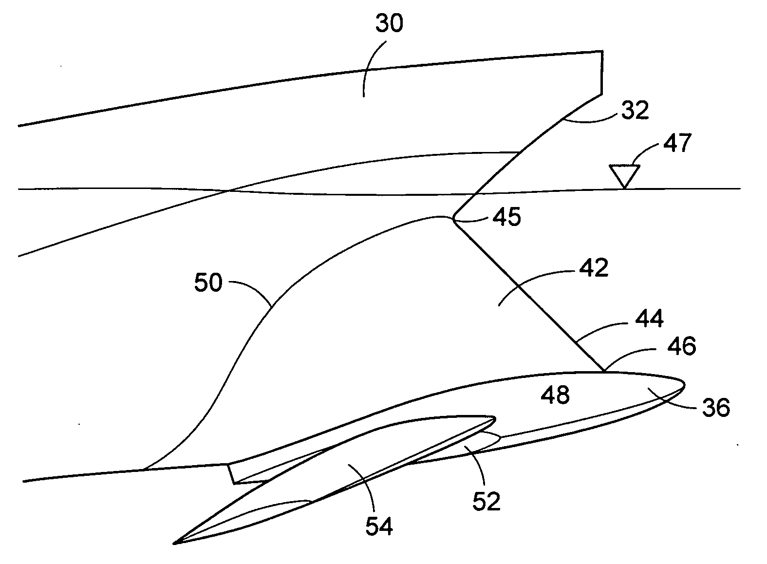
[0039]Referring now to the drawings in detail, and initially to FIGS. 7 and 8, two embodiments of watercrafts or ship hulls having a bow lifting body according to the present are illustrated. As seen in FIG. 7 a ship's hull 30 of conventional construction includes a tapered bow 32 and a bottom or keel 34. Secured to the bottom of bow 32 is a lifting body 36 formed in accordance with any of the embodiments of lifting bodies shown in FIGS. 1–6 and 13–27 of U.S. Pat. No. 6,263,819, although the embodiments of FIGS. 1 and 15 are currently preferred.

[0040]The lifting body 36 has a parabolic foil shape in longitudinal cross-section and a peripheral edge 38, referred to herein as the leading edge of the lifting body, which defines the widest portion of the body when viewed in plan. The edge is defined as a parabola substantially conforming to the conventional parabolic equation. The lifting body is generally symmetrical and longitudinal cross-sections taken parallel to its fore and aft axi...


PUM


Abstract

A watercraft having a hull, a fore and aft longitudinal axis and a bow includes a three dimensional low drag submerged lifting body secured to the bow below the design waterline of the hull.

Description

[0001]This application claims the benefit of U.S. Provisional Application No. 60 / 714,359 filed Sep. 7, 2005 and is a continuation-in-part of U.S. patent application Ser. No. 10 / 834,930 filed Apr. 30, 2004 now U.S. Pat. No. 7,004,093.FIELD OF THE INVENTION[0002]The present invention relates to ships and watercraft having improved efficiency and seakeeping from underwater submerged displacement hulls secured to the watercraft below its design waterline to act as a lifting body.BACKGROUND OF THE INVENTION[0003]In recent years a so-called Mid-Foil SWAS vessel was developed, as disclosed in U.S. Pat. No. 5,794,558, which uses a submerged underwater displacement hull or lifting body to provide lift to the craft in conjunction with any other parts of the vessel which generate lift. The lifting body differs from a hydrofoil in that the enclosed volume of the lifting body provides significant displacement or buoyant lift as well as hydrodynamic lift, whereas the lift of a hydrofoil is domina...

Claims


Application Information

Patent Timeline
Patent Type & Authority Patents(United States)
IPC IPC(8): B63B1/24
CPCB63B1/063B63B1/248Y02T70/126Y02T70/121B63B39/06Y02T70/10
Inventor LOUI, STEVENKEIPPER, TROYSHIMOZONO, GARYYAMASHITA, SCOTT
Owner HULL SCI RES LLC
Why Eureka
Try Eureka