Valve apparatus with seal assembly

a valve apparatus and seal technology, applied in the direction of sealing/packing, fluid removal, borehole/well accessories, etc., can solve the problems of cutting or clipping of the seal, and achieve the effect of preventing high differential pressure, soft sealing, and high volume flow ra

Active Publication Date: 2007-03-20
PETROQUIP ENERGY SERVICES
View PDF7 Cites 11 Cited by
  • Summary
  • Abstract
  • Description
  • Claims
  • Application Information

AI Technical Summary

Benefits of technology

[0018]An advantage of the present invention is that the valve of the present invention may be used as a sliding sleeve apparatus. Another advantage of the present invention is that the equalizing seal prevents high differential pressure and high volume flow rate from reaching the seal rings. Another advantage is that the equalizer seal comprises two seals—a dynamic seal ring and a static seal ring. Another advantage is that the seals provide gas tight soft seals. Still yet another advantage is that the equalizing seal provides linear thrust load that will energize the flanks of the seal rings and in turn create a soft seal.
[0019]Another advantage is that PEEK seal rings may be used, and the pressure rating of the valve can be raised. Another advantage is that by changing the direction of the seal stack will produce less damage and will not trap pressure between opposing seal faces. This will require the addition of another follower ring to provide a thrust load to energize the seal ring.
[0020]A feature of the present invention is that the follower seal provides bi-directional linear thrust load to energize the seal rings in both directions. Another feature is that the seating angle on each seal ring and header is designed to reduce the shifting force required to shift the sleeve with a high differential pressure across the seals. Yet another feature is that the optional back rings prevent extrusion into the adjacent seal ring.
[0021]Still yet another feature is the seal rings were designed with the minimal groove and a shallow tapered flank angle to allow for deflection of the seal ring. The flanks of the seals were designed as pressure vessels. Another feature is that the equalizing ports in the sleeve were designed to control the flow rate across the seal. In addition, the width of the grooves were also designed to prevent over stressing the seal rings.
[0022]Another feature is that the vent grooves are designed to prevent pressure from re-energizing the seal rings. In addition, the grooves are very shallow to prevent extrusion of the seal rings in the vent groove. Yet still another feature is that the seal assembly can be used with packers, chokes, jars and safety valves.

Problems solved by technology

One of the major problems with these prior art down hole devices is the seals.
The cause of the failure is generally cutting or clipping of the seals as the equalizing ports and the sleeve production ports pass under the seals.

Method used


Image

  • Valve apparatus with seal assembly
  • Valve apparatus with seal assembly
  • Valve apparatus with seal assembly

Examples


Embodiment Construction

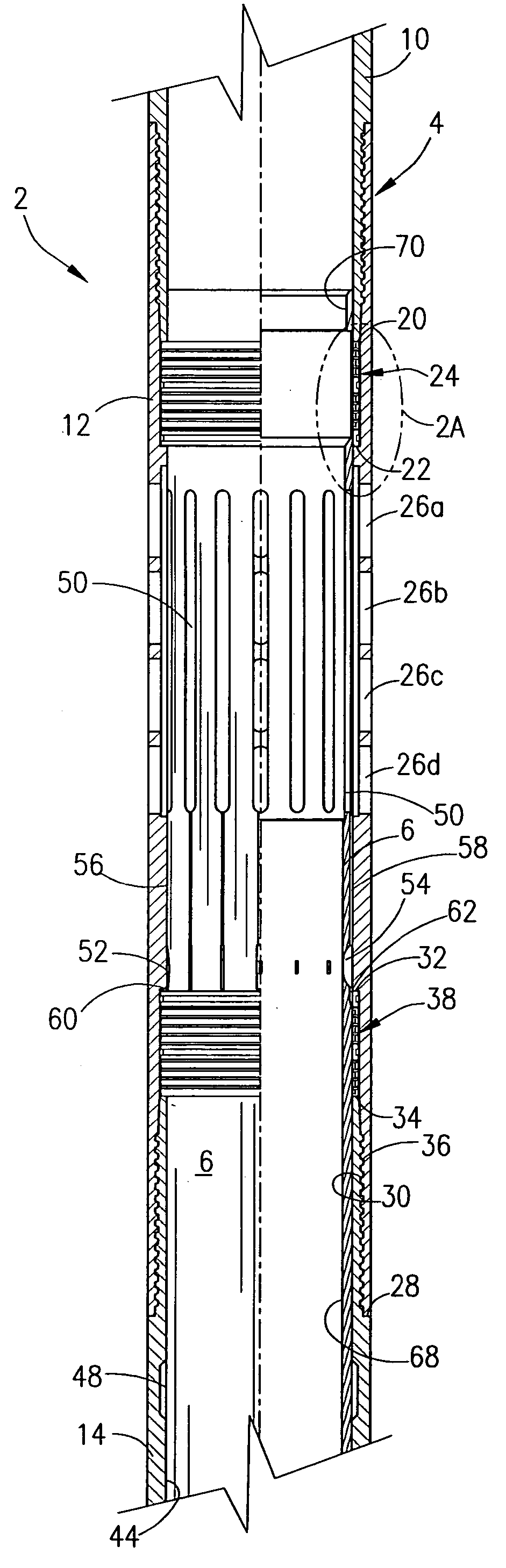
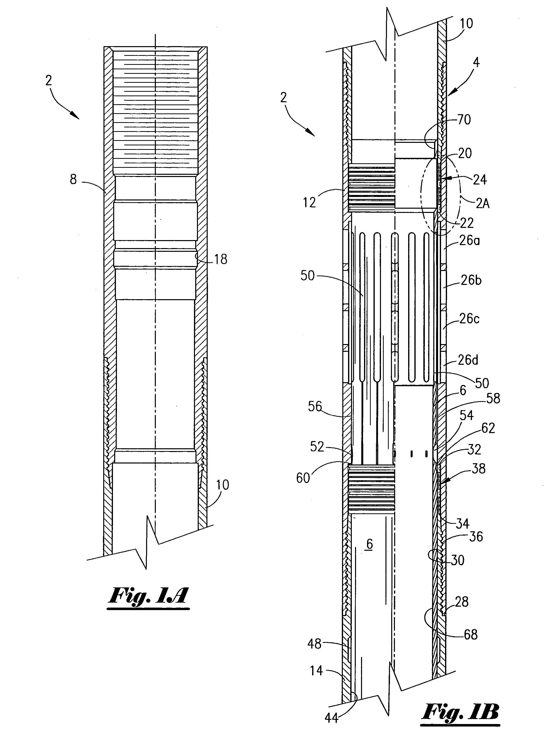
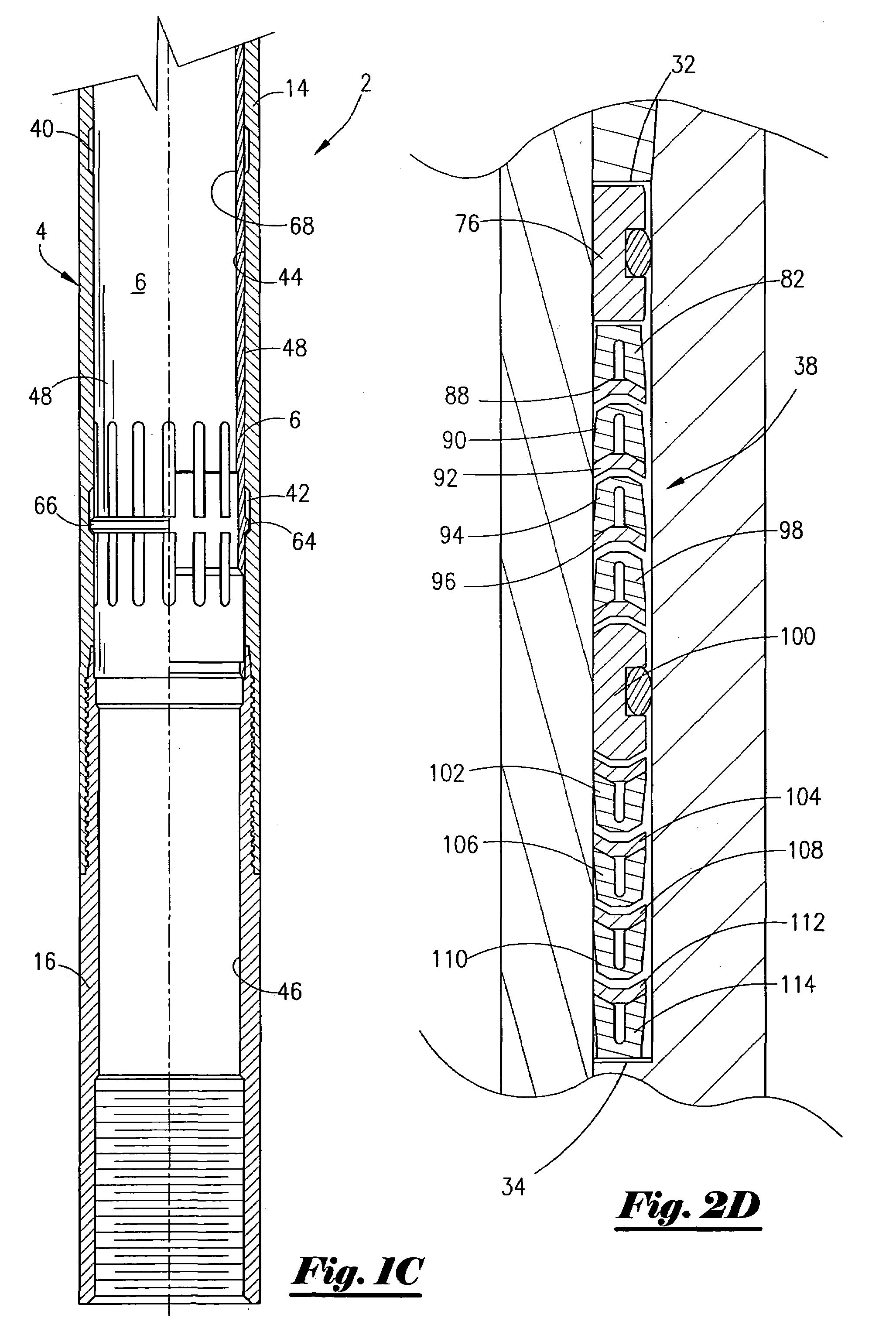
[0042]Referring now to FIGS. 1A–1C, a partial cross-sectional view of one of the preferred embodiment of the sliding sleeve assembly 2 in the open position will now be described. The assembly 2 includes an outer mandrel, seen generally at 4, as well an inner mandrel, seen generally at 6, and wherein the inner mandrel 6 is concentrically disposed within the outer mandrel 6. The outer mandrel 4 includes a first sub 8, second sub 10, third sub 12, fourth sub 14 and fifth sub 16 that are threadedly attached in series. The first sub 8 contains an internal locking nipple profile, seen generally at 18. The second sub 10 has a radial end 20. As shown in FIG. 1B, the third sub 12 is threadedly attached to the second sub 10. An internal shoulder 22 located on the third sub 12 will cooperate with the radial end 20 to form an indentation for a first seal assembly 24. The seal assembly 24 will be described in greater detail later in the application.

[0043]The third sub 12 contains a plurality of ...


PUM


Abstract

A valve apparatus. The valve apparatus is disposed within a well so that an annulus is formed between an outer portion of the valve and an inner portion of the well. In one preferred embodiment, the valve apparatus comprises an outer mandrel containing an annulus port; an inner mandrel slidably disposed within the outer mandrel, and wherein the inner mandrel contains a production and equalizing port. The valve contains a seal assembly so that pressure from the annulus is isolated from the inner portion of the inner mandrel. In one preferred embodiment, the seal assembly comprises: a first header seal; a first seal ring, abutting the header seal, for sealing with the outer portion of the inner mandrel; a follower seal abutting the seal ring; a second seal ring, abutting the follower seal, for sealing with the outer portion of the inner mandrel; a second header seal; and an equalizing seal abutting the second seal ring.

Description

BACKGROUND OF THE INVENTION[0001]This invention relates to a production control device. More particularly, but not by way of limitation, this invention relates to a production control device used in the production of hydrocarbons from subterranean reservoirs and its method of use.[0002]In the production of hydrocarbons from a well, operators may find it necessary to either open a port within a tubular string or close a port within a tubular string. A valve placed in a tubular string can be used to establish communication with the reservoir, or alternatively, to shut-off communication with the reservoir. Several devices have been developed over the years to accomplish the opening and / or closing of ports. These devices are generally known as sliding sleeves due to the ability to shift an inner sleeve from a first position to a second position. Sliding sleeves are commercially available from several vendors. One type of sliding sleeve that is commercially available is sold under the na...

Claims


Application Information

Patent Timeline
Patent Type & Authority Patents(United States)
IPC IPC(8): E21B34/14E21B34/06E21B34/10E21B43/12
CPCE21B43/12E21B34/101
Inventor WONG, FREDRICK SUN-VEOW
Owner PETROQUIP ENERGY SERVICES
Why Eureka
Try Eureka