Emitter array configurations for a stationary CT system

a technology of emitter array and emitter array, which is applied in the field of field emitter array and field emitter array systems, can solve the problems of unavoidable leakage rate associated with any feedthrough device, complexity of sct system, etc., and achieve the effect of reducing the complexity and manufacturing cost of x-ray sources, minimizing the number of feedthroughs of x-ray sources, and reducing the complexity of x-ray sources

Active Publication Date: 2007-03-20
GE MEDICAL SYST GLOBAL TECH CO LLC
View PDF5 Cites 92 Cited by
  • Summary
  • Abstract
  • Description
  • Claims
  • Application Information

AI Technical Summary

Benefits of technology

[0009]The embodiments of the present invention provide several advantages. One such advantage is the provision of an x-ray source having an emitter array where each emitter element therein has multiple activation connections. In so doing, the stated embodiment minimizes the number of activation control lines for the emitter array and thus, the number of feedthroughs from atmosphere into the vacuum of the x-ray source. The reduction in the number of activation lines and feedthroughs reduces the complexity and manufacturing costs of the x-ray source.
[0010]Another advantage provided by an embodiment of the present invention, is the provision of mapping two-dimensional and three-dimensional activation schemes to one-dimensional physical configurations. This allows for the generation of arc-shaped emitter arrays having minimal activation control lines.
[0011]Yet another advantage provided by an embodiment of the present invention, is the provision of an x-ray source having multiple emitter array blocks, each of which having associated address lines. This further minimizes the number of feedthroughs of an x-ray source.

Problems solved by technology

Such a system requires a large vacuum system to enclose the electron beam trajectory and a complicated beam deflection system, to accurately steer the beam.
However, although the complexity of high voltage high power x-ray tubes is generally due to the vacuum enclosure and the careful preparation of the surfaces and volumes of material that are enclosed therein, the complexity of an SCT system can also be due to the number of activation lines and connections associated with the large number of emitter elements of an emitter array.
There is an unavoidable leak rate associated with any feedthrough device.

Method used


Image

  • Emitter array configurations for a stationary CT system
  • Emitter array configurations for a stationary CT system
  • Emitter array configurations for a stationary CT system

Examples


Embodiment Construction

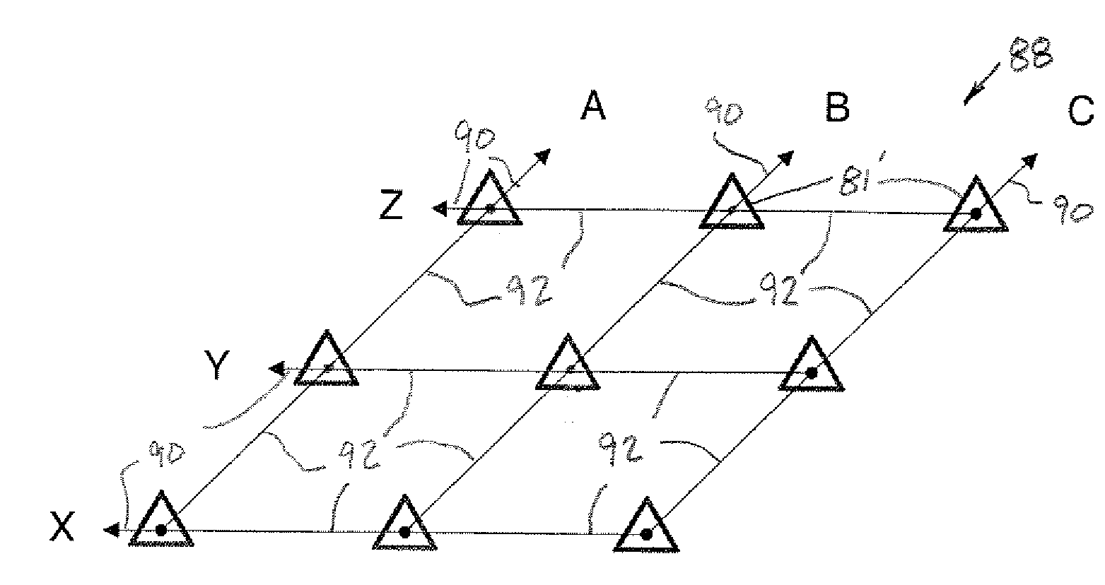
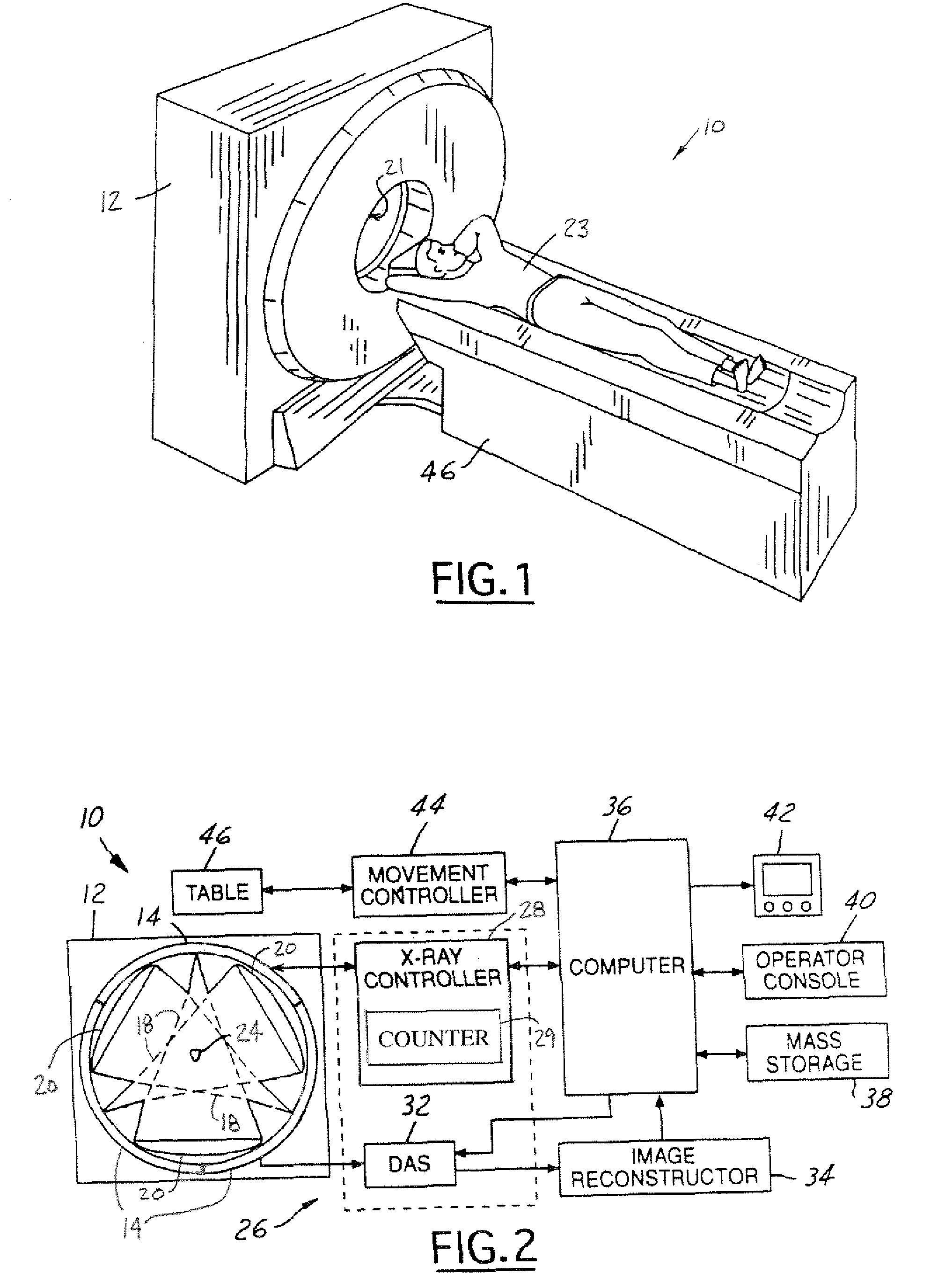
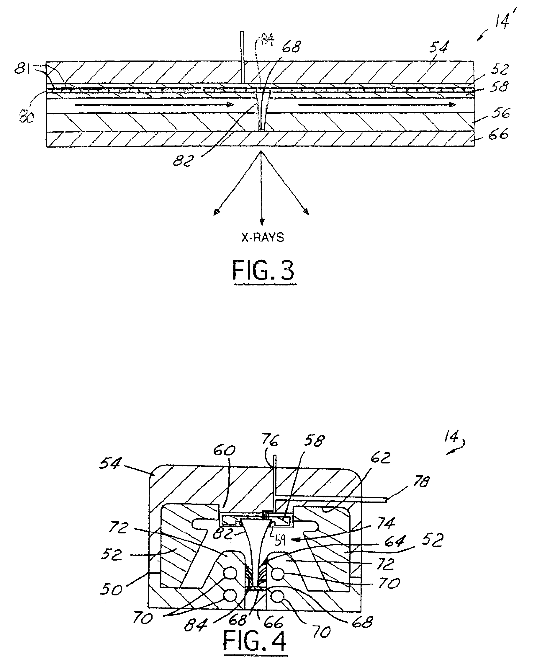
[0025]In the following figures the same reference numerals will be used to refer to the same components. While the present invention is described with respect to x-ray source emitter array configurations utilized within a stationary computed tomography (SCT) system, the present invention may be adapted and applied to various systems including CT systems having a rotating gantry and other x-ray systems that utilize emitter arrays. The present invention may also be applied to flat panel displays and other systems, which include field emitter arrays.

[0026]In the following description, various operating parameters and components are described for one constructed embodiment. These specific parameters and components are included as examples and are not meant to be limiting.

[0027]Although the embodiments of FIGS. 1–4 are described below with respect to a stationary gantry, the present invention may be applied to a rotating gantry. For example, a gantry may be rotated at a slow rate while u...


PUM


Abstract

An field emitter array system (10) includes a housing (50). An emitter array (80) generates an electron beam and has multiple emitter elements (81) that are disposed within the housing (50). Each of the emitter elements has multiple activation connections (92).

Description

BACKGROUND OF INVENTION[0001]The present invention relates generally to field emitter arrays and field emitter array systems, such as computed tomography (CT) imaging systems. More particularly, the present invention relates to emitter array configurations for field emitter array systems.[0002]A CT imaging system typically includes a gantry that rotates at various speeds to create 2D and 3D images. The gantry contains an x-ray source, such as an x-ray tube that generates x-rays across a vacuum gap between a cathode and an anode. The x-ray source projects a fan-shaped beam that is collimated to lie within an X-Y plane of a Cartesian coordinate system, which is generally referred to as the “imaging plane”. The x-ray beam passes through the object being imaged, such as a patient. The beam, after being attenuated by the object, impinges upon an array of radiation detectors. Each detector element of the array produces a separate electrical signal that is a measurement of the beam attenua...

Claims


Application Information

Patent Timeline
Patent Type & Authority Patents(United States)
IPC IPC(8): H01J35/00H01J35/06G21K5/02A61B6/03G21K5/04H01J35/14H01J35/22H01J35/32H05G1/60
CPCA61B6/032A61B6/4028A61B6/4488H01J35/14H01J35/065H01J2235/06H01J2235/02H01J35/147
Inventor DUNHAM, BRUCE M.WILSON, COLIN R.PRICE, JOHN SCOTT
Owner GE MEDICAL SYST GLOBAL TECH CO LLC
Why Eureka
Try Eureka