Coupling flange system for hollow shaft

Active Publication Date: 2007-03-20
EUROCOPTER
View PDF7 Cites 7 Cited by
  • Summary
  • Abstract
  • Description
  • Claims
  • Application Information

AI Technical Summary

Benefits of technology

[0012]This invention aims to remedy these drawbacks and refers to a coupling flange system, the design of which allows the flan

Problems solved by technology

Although widely used, these two solutions nevertheless have drawbacks that cannot be left out of consideration.
In the first case, the weak spot is at the holes for riveting or bolting arranged radially at the shaft end, leading to local over-stressing that is always detrimental, in particular for the dynamic forces encountered on a helicopter (change of power level related to tail rotor maneuvering).
In the second case, welding causes a drop in the fatigue strength of the materials because of the annealing of the welding parts, making it necessary to allow for extra-thickness in the welding zone.
Furthermore, once attached to the ends of the shafts, the flanges cannot be removed (weld) or are almost irremovable (bonding and riveting-bol

Method used


Image

  • Coupling flange system for hollow shaft
  • Coupling flange system for hollow shaft
  • Coupling flange system for hollow shaft

Examples


first embodiment

[0047]In these two embodiments, the flange system structure, i.e. flange 5 with housing 507, 607, the set of external and internal conical rings, the annular space 10 and the clamping device 11, as well as its assembly and mounting on the tubular end of shaft 2, are identical to the first embodiment described above and will not be explained in any greater detail.

second embodiment

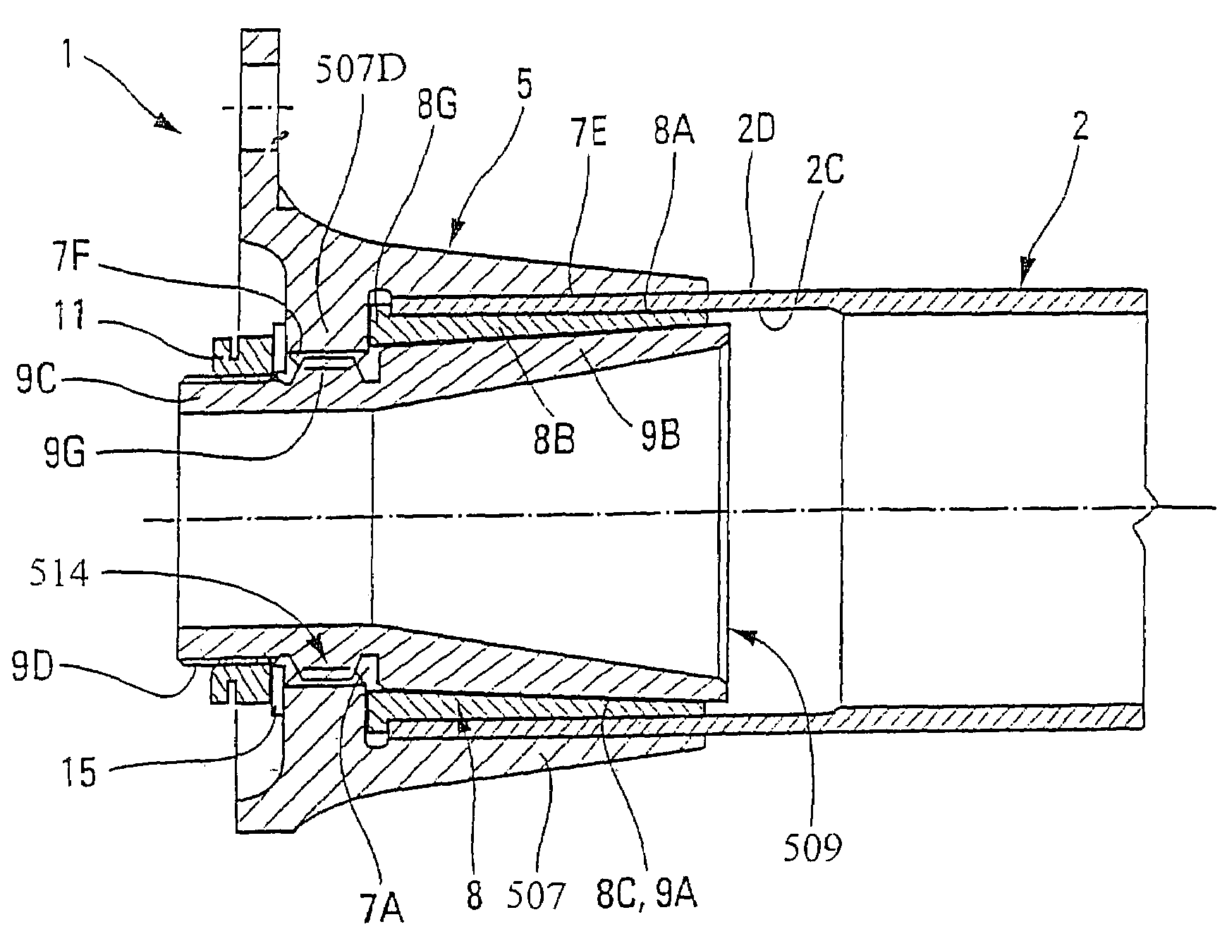
[0048]In the second embodiment illustrated in FIG. 5, the rotating link 514 is of the obstacle-drive type and comprises a multitude of teeth 7F (or ribbing) arranged on the inner perimeter of internal annular shoulder 507D of rigid housing 507 and a multitude of complementary teeth 9G on the outside of the inner ring, corresponding with said internal annular shoulder 507D between threading 9D and the truncated wall 9B of internal conical ring 509. The rotating link, through two teeth 7F–9G, radially connecting housing 507 of flange 5 to internal conical ring 509 of the assembly, allows considerable torque to be passed to shaft 2 by the inner ring, the combined truncated surfaces and the outer ring. A washer 15 is also provided between clamping device 11 and link 514 to ensure a sufficient bearing capacity of clamping device 11 on internal annular shoulder 507D.

third embodiment

[0049]In the third embodiment shown in FIG. 6, the rotary link 614 is of the friction drive type comprising a plate 16 attached to housing 607 and internal conical ring 609. More particularly, plate 16 is applied to the transversal face 7G of base 7B and the transversal face 9H of internal conical ring 609, while the two transversal faces 7G and 9H are contained more or less within the same plane, perpendicular to the axis of flange system 1. An adjusting shim, not shown, could be introduced advantageously between plate 16 and faces 7G or 9H respectively of housing 7 and the internal conical ring to ensure the assembly of the components 16, 7 and 609, without any play or spurious flexing forces. It is also evident that the transversal face of internal conical ring 609 is solid so as to be able to attach plate 16 to it with screws 17, whereas attachment of the plate to base 7B is by means of bolts 12, not shown, in coupling A. Therefore, plate 16 is arranged between the elastic disk ...


PUM


Abstract

The system is of a type including a flange (5) and a set of conical internal rings (9) and external rings (8) combined to link by friction the flange to the shaft through the relative axial movement of the rings. Advantageously, the flange includes a rigid housing (7) with a cylindrical axial passage (7A) to receive coaxially the set of conical rings (8,9) and define between the inner surface of the passage (7A) and the outer surface of the external ring (8) an annular space (10) in which can be engaged the end (2A) of the shaft and of which the external ring (8) is elastically and radially deformable.

Description

BACKGROUND OF THE INVENTION[0001]This invention concerns a coupling flange system providing interconnection between hollow or similar transmission shafts connecting together two power devices or machines, respectively the motor and the receiver, distant from one another.[0002]A typical case is power transmission in a rotary wing aircraft like a helicopter, connecting the main rotor transmission box to the anti-torque tail rotor transmission box. Because of the distance between the two boxes (several meters), transmission comprises several aligned shafts supported by bearings along the transmission line and coupled together, and with the respective drive and receiver shaft. To do this, the ends facing the two shafts, extending one another, are equipped with flanges which, by a link connecting them together, form a coupling or coupling sleeve as such, which link between the flanges in this example is elastic and, more particularly to compensate for the slight deformations and aligning...

Claims


Application Information

Patent Timeline
IPC IPC(8): B60B27/00F16D1/09F16D1/091
CPCF16D1/09F16D2001/0903Y10T403/10Y10T403/7056Y10T403/7058F16C3/023
Inventor MERMOZ, EMMANUEL
Owner EUROCOPTER
Why Eureka
Try Eureka