
Direct recharge injection of underground water reservoirs

a technology of underground water reservoirs and direct injection, which is applied in the direction of mechanical equipment, transportation and packaging, service pipe systems, etc., can solve the problems of increasing the difficulty of building conventional open reservoirs for the storage of water, severely curtailing the flow of water downstream, and becoming prohibitively difficult to form an open reservoir in this manner. , to achieve the effect of effectively discharging water and reducing temperature impacts

Active Publication Date: 2007-03-20
PS SYST
View PDF44 Cites 18 Cited by
  • Summary
  • Abstract
  • Description
  • Claims
  • Application Information

AI Technical Summary

Benefits of technology

The system effectively reduces evaporative losses, minimizes contamination risks, and maintains water quality by using naturally filtered sediment-free water and temperature-controlled discharge, enhancing the efficiency and sustainability of water storage.

Problems solved by technology

It is becoming increasingly difficult, both in terms of cost and site availability, to construct conventional open reservoirs for the storage of water.
Such reservoirs typically require the construction of a dam across a river, thereby flooding vast expanses of land upstream of the dam while severely curtailing the flow of water downstream from the dam.
In light of the increasing value of water and the complexities of the various water laws across different jurisdictions, it is becoming prohibitively difficult to form an open reservoir in this manner.
One disadvantage is that they preempt any current or future use of the land other than to store water.
That is, as additional land surface is devoted to the storage of water in open reservoirs, that same land surface is unavailable for alternative uses such as farming or open space.
A further disadvantage of storing water in open reservoirs is the high degree of evaporative losses experienced by such reservoirs due to the relatively large air / water interface.
Specifically, in arid climates (such as those found in the Western United States), open reservoirs are subject to extremely large evaporative losses.
Indeed, such evaporative losses are typically greatest where water is needed most.
A further unfortunate disadvantage to open reservoirs is that the reservoirs are highly susceptible to contamination.
While previous contamination concerns have been limited to accidental chemical spills, petroleum leaks, polluted surface-water runoff, and the like, a more immediate threat is that of intentional contamination as part of a terrorist act.
Yet another disadvantage relates to detrimental temperature effects caused by surface water storage.
Discharge of the warm water from the reservoir could then damage the downstream fish populations.
However, underground porosity water reservoirs also have drawbacks when used for water storage.
First, typical water diversion techniques suitable for filling open reservoirs, such as direct pumping from a surface water body or the use of surface diversion ditches, reduce the potential benefits of underground reservoirs.
The use of existing diversion ditches directly impacts surface uses near a reservoir site and therefore reduce one major benefit of underground reservoirs.
Additionally, surface ditches, which are typically unlined because of cost, increase the passive loss of water due to evaporation and infiltration, thus reducing another major benefit of underground reservoirs.
Furthermore, the diversion techniques mentioned above typically increase the sediment load in the water, which, as discussed below, is another factor that makes typical diversion techniques undesirable for use with underground reservoirs.
If water injected into an underground reservoir has a high sediment load, the alluvium surrounding the injection points may be clogged, reducing the effectiveness of the underground reservoir and reducing the storage capacity of the reservoir.
However, settling ponds represent a significant impact on surface use of the reservoir site and are undesirable for use in sites where impacts on surface uses are to be minimized.
Third, not all alluvium is chemically inert, and thus water injected into an underground reservoir may contain dissolved chemicals that react with the alluvium or porous material that provides the porosity of the underground reservoir.
This reaction could cause a precipitate to form that fouls the underground reservoir or changes the character of the water thereby rendering the stored water useless for its intended purpose.

Method used


Image

  • Direct recharge injection of underground water reservoirs
  • Direct recharge injection of underground water reservoirs
  • Direct recharge injection of underground water reservoirs

Examples


Embodiment Construction

[0023]Embodiments of the present invention include underground porosity reservoir systems and methods that minimize impact to surface uses while also improving the quality of water drawn from surface water bodies for storage in the underground reservoirs. Embodiments also include underground porosity reservoir systems and methods that reduce the impact on surface water bodies due to the discharge of stored water.

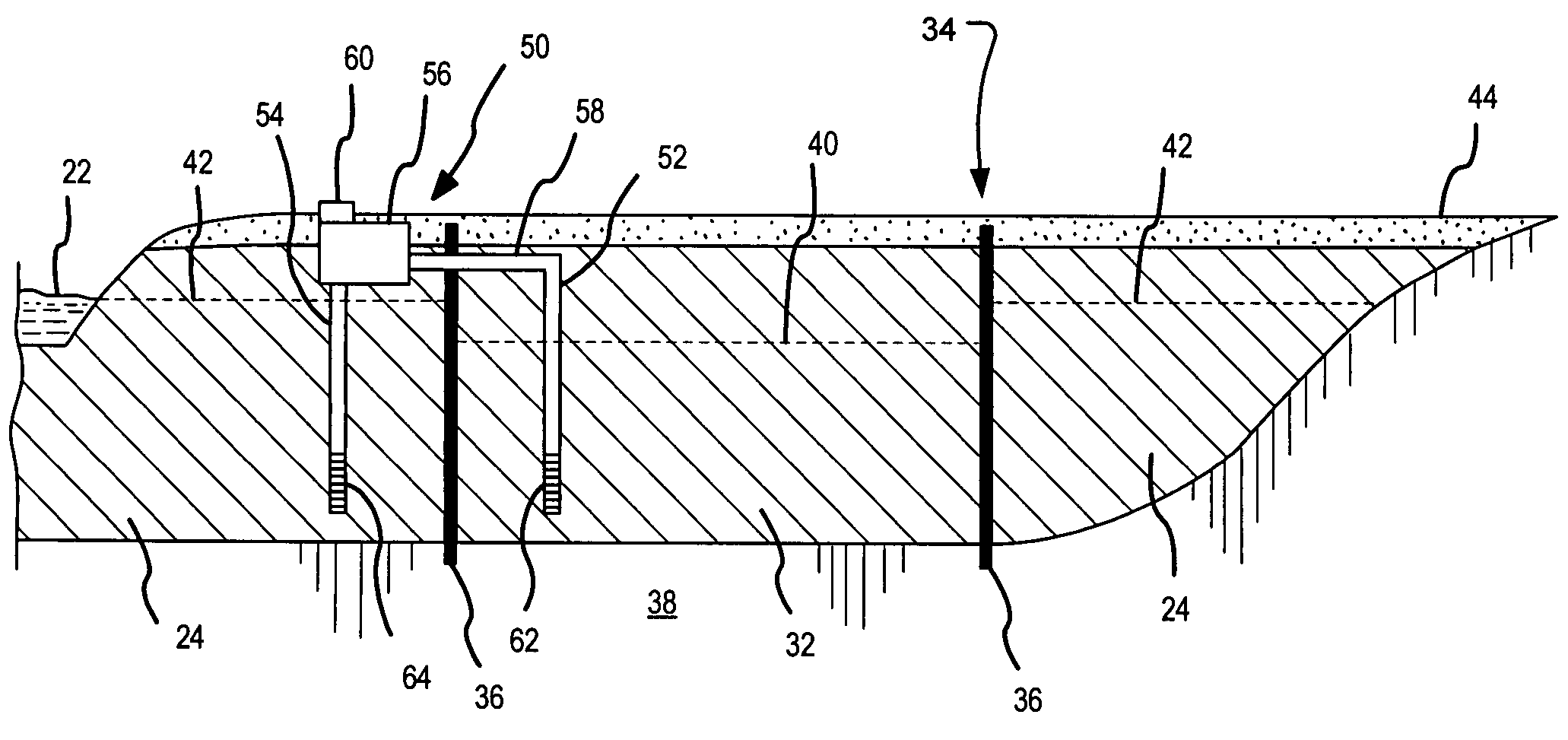
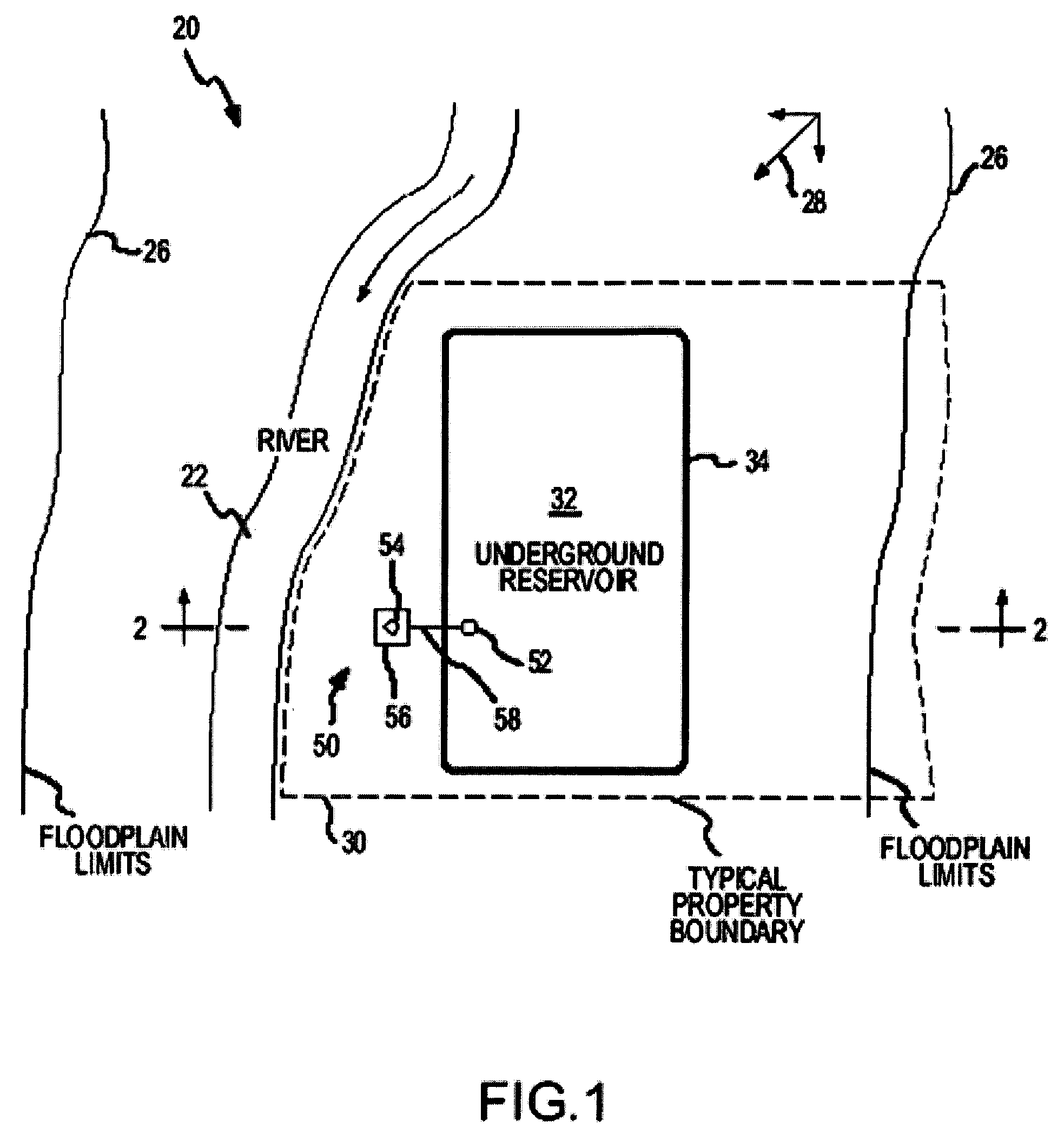
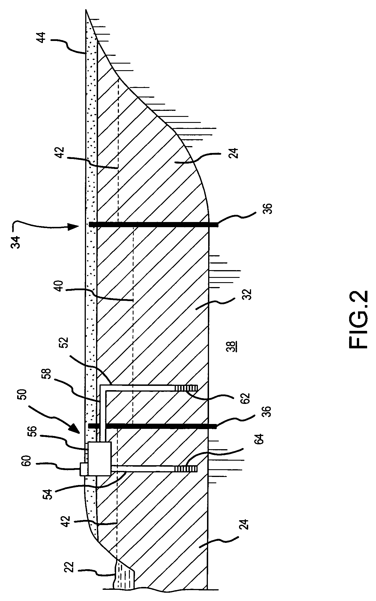
[0024]FIGS. 1 and 2 illustrate an exemplary underground reservoir system in accordance with the present invention. FIG. 1 illustrates a plan view of an exemplary river system or basin 20 comprising a riverbed 22 that flows along the top of alluvial deposits 24 (FIG. 2), e.g., sand and gravel, formed within the boundary 26 of a floodplain that extends to either side of the current riverbed 22. An arrow 28 in FIG. 1 illustrates a direction of flow of the groundwater through the alluvial deposits 24. A dashed line 30 further illustrates a typical property line of a parcel of la...


PUM


Abstract

An underground porosity water storage reservoir minimizes the impacts on surface uses of the reservoir site. Furthermore, a method of operating an underground porosity storage reservoir minimizes damage to the reservoir due to injecting sediment-laden water or water that is chemically incompatible with the porous material in the underground reservoir. The underground porosity water storage reservoir reduces temperature impacts on surface waters due to the discharge of stored water. A method of using the porosity storage reservoir to minimize adverse temperature impacts when discharging water to a surface body is disclosed.

Description

RELATED APPLICATIONS[0001]The application claims priority from U.S. Provisional Application No. 60 / 547,496, filed Feb. 24, 2004, which is hereby incorporated herein by reference.FIELD OF THE INVENTION[0002]This application relates generally to a method of operating a water storage facility and more particularly to a method of operating a water storage facility that includes one or more underground alluvial water storage reservoirs.BACKGROUND OF THE INVENTION[0003]It is becoming increasingly difficult, both in terms of cost and site availability, to construct conventional open reservoirs for the storage of water. Such reservoirs typically require the construction of a dam across a river, thereby flooding vast expanses of land upstream of the dam while severely curtailing the flow of water downstream from the dam. In light of the increasing value of water and the complexities of the various water laws across different jurisdictions, it is becoming prohibitively difficult to form an op...

Claims


Application Information

Patent Timeline
Patent Type & Authority Patents(United States)
IPC IPC(8): B65G5/00E03B3/36E03B11/14
CPCB65G5/005E03B11/14E03B3/36Y10T137/402Y02A20/00E02B3/041
Inventor PETERS, STANLEY R.SUMMERS, DONALD O.
Owner PS SYST
Learn More