
Enhanced floating reference frame controller for sensorless control of synchronous machines

a reference frame controller and synchronous machine technology, applied in the direction of dynamo-electric converter control, motor/generator/converter stopper, instrument, etc., can solve the problems of unreliable rotor position sensors, loss of synchronization with the synchronous motor, and difficult mounting of rotor position sensors to the motor

Active Publication Date: 2007-03-20
HONEYWELL INT INC
View PDF10 Cites 30 Cited by
  • Summary
  • Abstract
  • Description
  • Claims
  • Application Information

AI Technical Summary

Benefits of technology

The present invention provides a method and system for controlling a polyphase synchronous machine that allows for resynchronization after a power interrupt and adjustable power factor for sensorless control. This is achieved by measuring line currents and back emf, selecting a floating reference frame for the current Park vector, adjusting the reference frame based on an estimated rotor speed, and controlling the power converter via the floating reference frame to reinitiate power to a motor or a generator while a rotor is still moving.

Problems solved by technology

However, rotor position sensors can be unreliable due to mechanical alignment problems (e.g., problems caused by bearings) and temperature incompatibility problems between the stator windings and electronic components such as the Hall effect devices.
Moreover, the rotor position sensors can be difficult to mount to the motor during motor assembly, especially for multi-pole motors.
In such a sensorless control system, if there is a power interrupt to the controller, the synchronization with the synchronous motor can be lost.
When the power comes back on and the rotor is still spinning, if the inverter were to try to synchronize with the synchronous machine to initiate the drive, a current value exceeding the rated current can flow through the synchronous machine causing trauma to the electronic components of the controller.
For example, power semiconductor switches such as IGBTs can be damaged.
For example, for large drives this can take tens of seconds.

Method used


Image

  • Enhanced floating reference frame controller for sensorless control of synchronous machines
  • Enhanced floating reference frame controller for sensorless control of synchronous machines
  • Enhanced floating reference frame controller for sensorless control of synchronous machines

Examples


Embodiment Construction

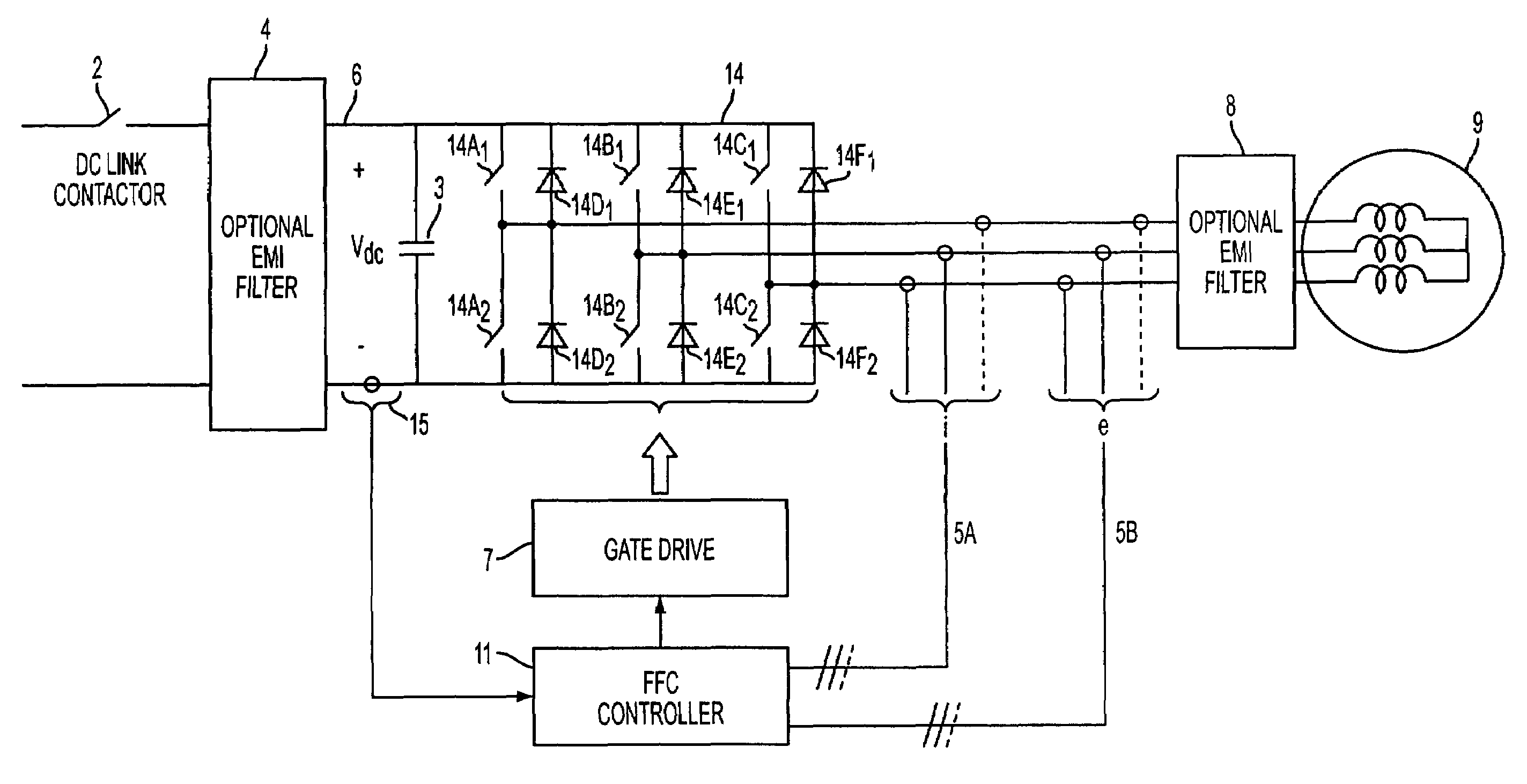
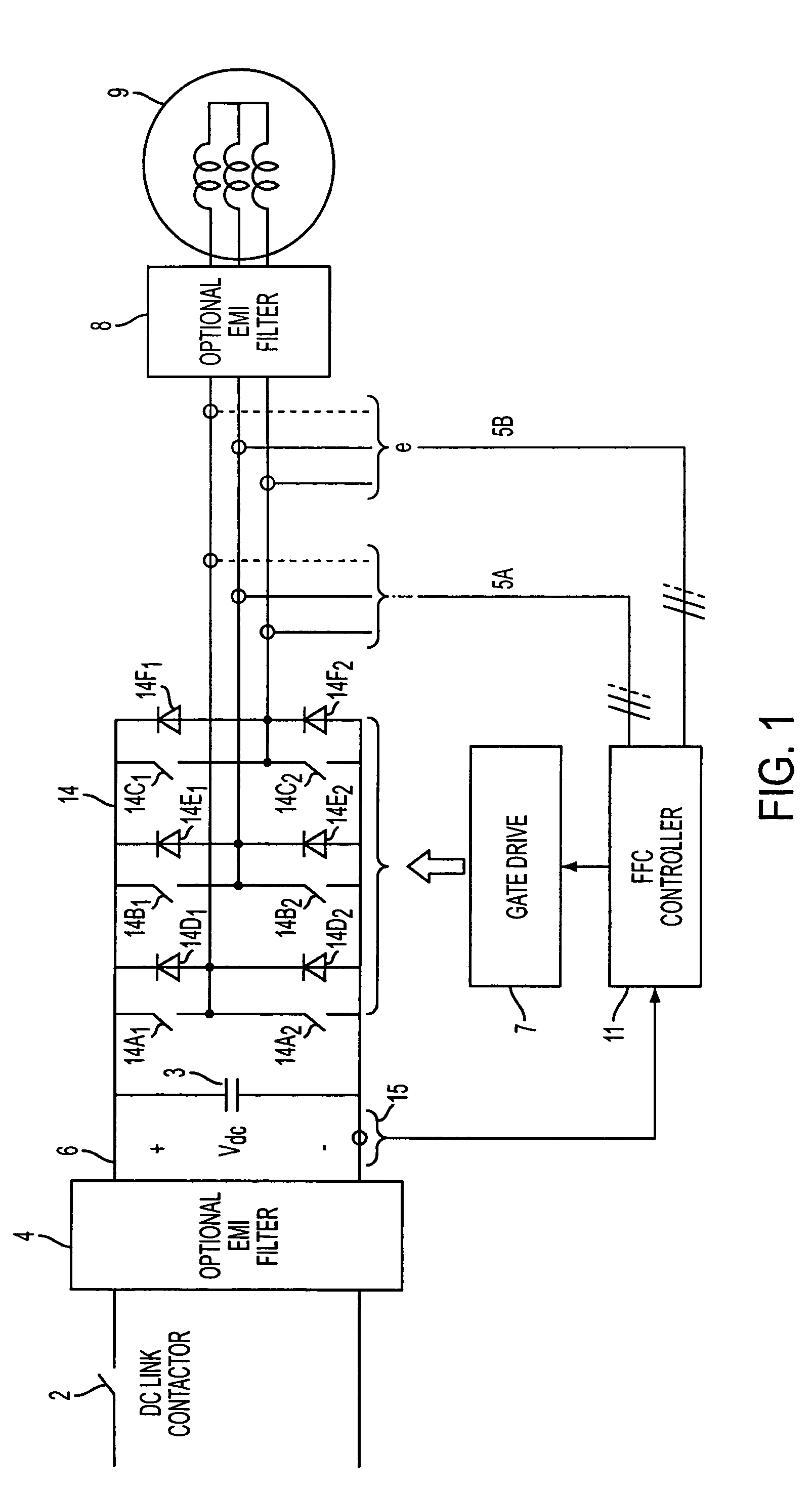
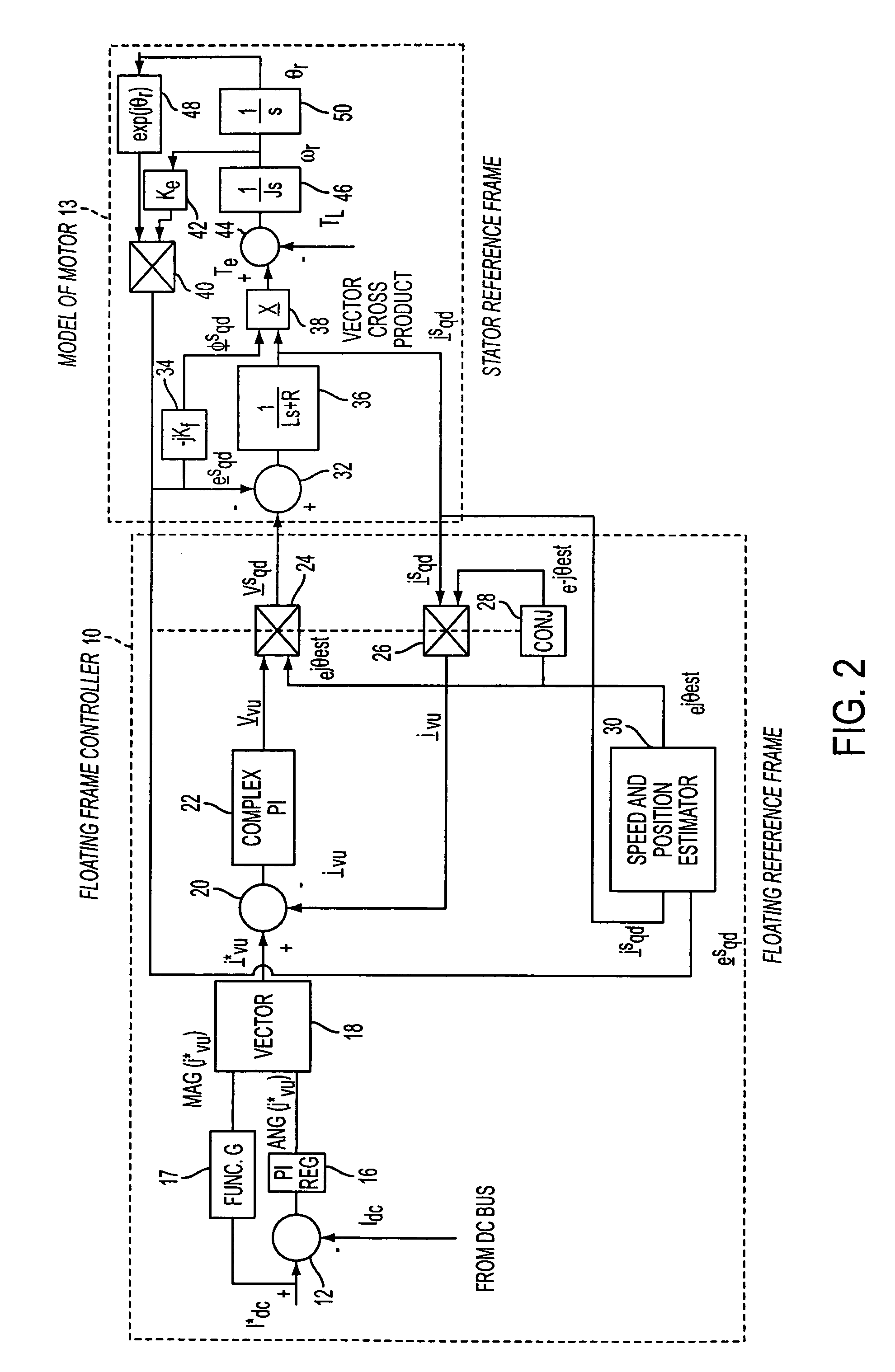
[0021]The embodiment of the invention described below includes a system and method for reinitiating power without inducing adverse effects to a power converter and electrical machine while the rotor is still moving.

[0022]FIG. 1 is a block diagram of a power converter in accordance with an embodiment of the present invention. FIG. 1 comprises a DC current sensor 15, a DC link contactor 2, a first filter 4, a DC link 6, a capacitor 3, an inverter 14, a second filter 8, an electrical motor 9, a gate drive 7, the floating frame controller 11, and AC current and voltage sensors 5. The DC link 6 provides the low source impedance for the inverter 14, and is used to synthesize a pulse width modulated AC output voltage using the inverter 14. The inverter 14 may be a three-phase bridge inverter. Such an inverter includes six switches: a set of upper switches and a set of lower switches. Each switch of the inverter includes a controllable solid-state device (e.g., an IGBT, a MOSFET) and an ant...


PUM


Abstract

A method and system for controlling a power converter coupled to a polyphase power line. The method includes measuring at least two motor phase currents, obtaining a floating reference frame for the current Park vector, adjusting the reference frame based on an estimated rotor speed, and controlling the power converter via the floating reference frame to reinitiate power to a motor while a rotor is still moving.

Description

REFERENCE TO RELATED APPLICATIONS[0001]Related subject matter is disclosed in U.S. Pat. No. 6,301,136, issued on Oct. 9, 2001, entitled “Floating Frame Controller”, and U.S. Patent Application Publication No. 2004 / 0021447, entitled “Voltage Control Of An HR-PMG Without A Rotor Position Sensor”, the entire contents of which is incorporated herein by reference.BACKGROUND OF THE INVENTION[0002]1. Field of the Invention[0003]The invention relates to a method and apparatus for performing electrical power conversion. More particularly, the present invention relates to a method and apparatus for resynchronizing a power converter such as an inverter without using a rotor position sensor.[0004]2. Description of the Related Art[0005]A conventional synchronous motor typically uses rotor position sensors to provide information regarding the position of the motor's rotor with respect to the motor's stator windings to achieve control of the speed and torque. Rotor position sensors such as Hall ef...

Claims


Application Information

Patent Timeline
Patent Type & Authority Patents(United States)
IPC IPC(8): G05F1/70
CPCH02P1/029H02P6/182H02P21/12H02P9/009H02P21/0053H02P6/22H02P21/32
Inventor SARLIOGLU, BULENTHUGGETT, COLIN E.
Owner HONEYWELL INT INC
Learn More