Radio frequency cavity resonator with heat transport apparatus

a cavity resonator and radio frequency technology, applied in the direction of waveguide devices, resonators, basic electric elements, etc., can solve the problems of adversely affecting the resonant frequency and affecting the performance of the rf cavity resonator

Active Publication Date: 2007-03-20
MOTOROLA SOLUTIONS INC
View PDF7 Cites 11 Cited by
  • Summary
  • Abstract
  • Description
  • Claims
  • Application Information

AI Technical Summary

Benefits of technology

[0039]While the invention has been described in conjunction with specific embodiments thereof, additional advantages and modifications will readily occur to those skilled in the art. The invention, in its broader aspects, is therefore not limited to the specific details, representative apparatus, and illustrative examples shown and described. Various alterations, modifications and variations will be apparent to those skilled in the art in light of the foregoing description. Thus, it should be understood that the invention is not limited by the foregoing description, but embraces all such alterations, modifications and variations in accordance with the spirit and scope of the appended claims.

Problems solved by technology

When used in high power applications, such as in transmitters, some of the RF cavity resonator's elemental parts are typically subject to extreme temperature variations.
For instance, as power is introduced into the RF cavity resonator, these elemental parts may heat up to temperatures that adversely affect the performance of the RF cavity resonator.
This will typically cause the resonant frequency of the RF cavity resonator to become unstable, thereby affecting the performance of an RF device that incorporates the RF cavity resonator.
If the RF cavity resonator is also operating in high ambient temperatures, this will worsen the stability problem.
Moreover, in a worst case scenario, the elemental components of the RF cavity resonator may heat to the point of failure.
To address the instability of RF cavity resonators under high power and high ambient temperature conditions, RF device designers may compromise between the power handling capability and operating temperature of a product that incorporates the RF cavity resonator.
However, this in turn leads to a compromise in the performance specifications of the product.
However, these techniques may utilize extruded heat sinks that appreciably increase the size and weight of the product.
Moreover, these design techniques typically result in an increased design cycle time and may also require significant preconditioning during the manufacturing process that increases the end-product cost.
In addition, conventional temperature compensation techniques, in general, do not provide a solution for the entire operating range of the product.

Method used


Image

  • Radio frequency cavity resonator with heat transport apparatus
  • Radio frequency cavity resonator with heat transport apparatus
  • Radio frequency cavity resonator with heat transport apparatus

Examples


Embodiment Construction

[0013]While this invention is susceptible of embodiments in many different forms, there are shown in the figures and will herein be described in detail specific embodiments, with the understanding that the present disclosure is to be considered as an example of the principles of the invention and not intended to limit the invention to the specific embodiments shown and described. Further, the terms and words used herein are not to be considered limiting, but rather merely descriptive. It will also be appreciated that for simplicity and clarity of illustration, elements shown in the figures have not necessarily been drawn to scale. For example, the dimensions of some of the elements are exaggerated relative to each other. Further, where considered appropriate, reference numerals have been repeated among the figures to indicate corresponding elements.

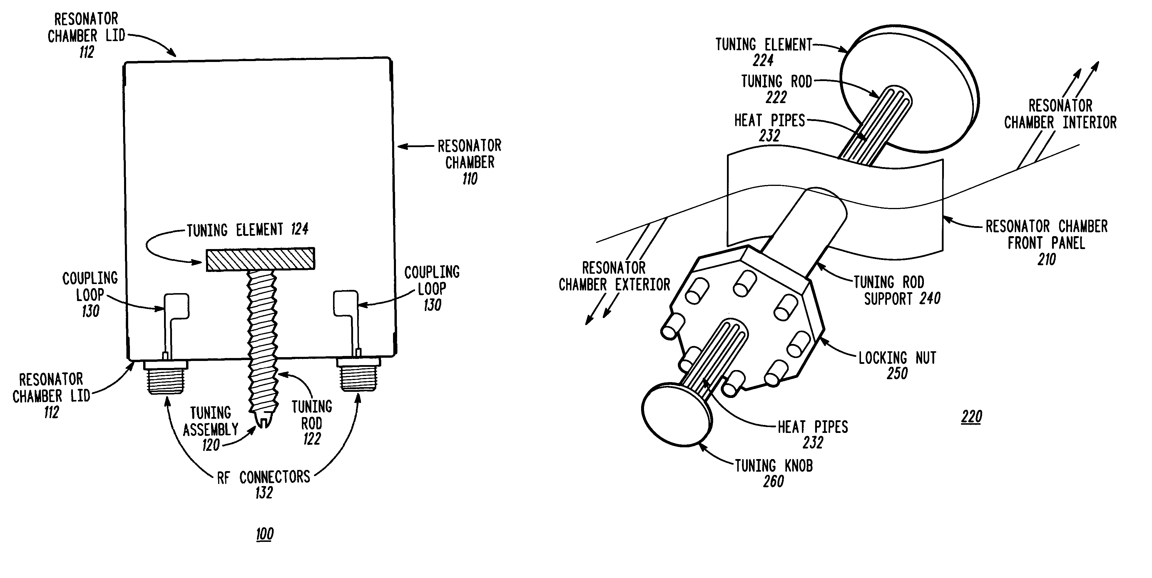
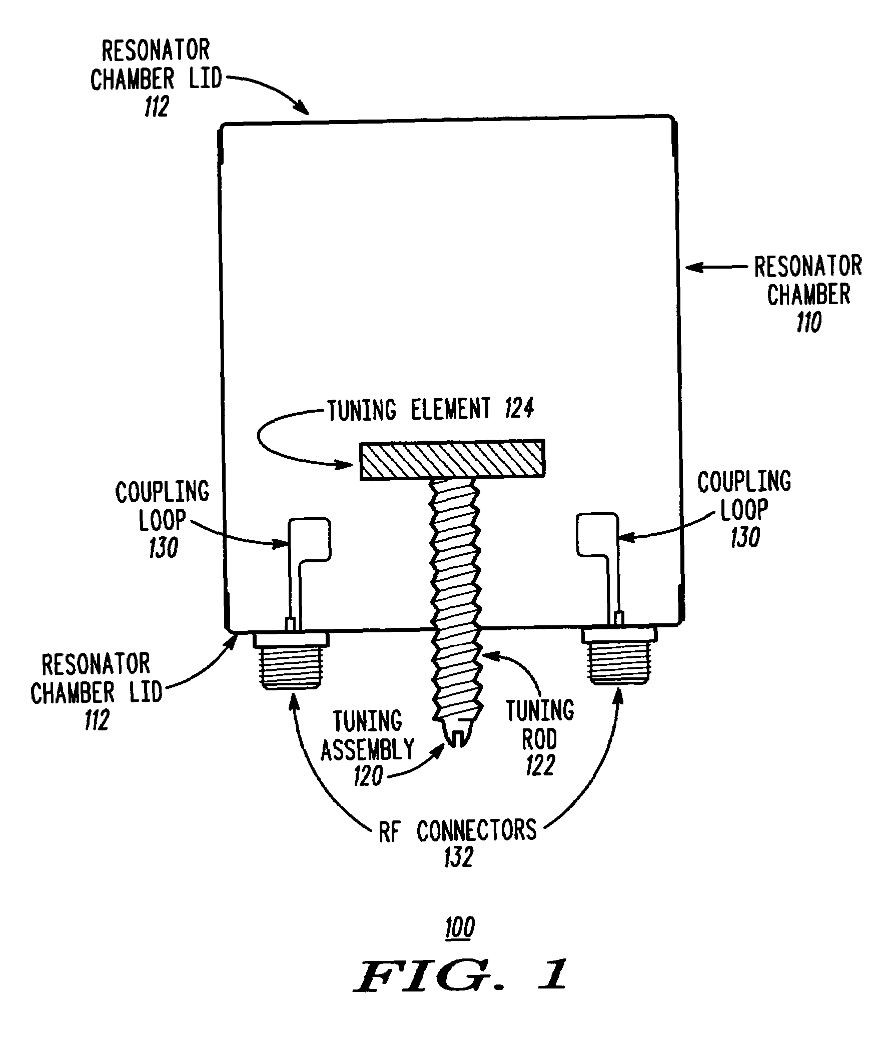
[0014]FIG. 1 illustrates a cross-sectional view of an RF cavity resonator 100 in accordance with an embodiment of the present invention....


PUM


Abstract

An RF cavity resonator (400) that includes: a resonator chamber (410) for containing an RF field; an RF coupling element (450, 452) coupled to the resonator chamber for introducing the RF field into and extracting the RF field from the resonator chamber; a tuning assembly (420) for causing the RF field to resonate at a desired frequency, wherein at least a portion of the tuning assembly is coupled within the resonator chamber; and a heat transport element (440) for transporting heat from the RF cavity resonator, wherein at least a portion of the heat transport element is coupled within the resonator chamber, the heat transport element including a phase change material, a housing for enclosing the phase change material, means for circulating the phase change material within the housing, and an electrically conductive surface for isolating the phase change material from the RF field.

Description

FIELD OF THE INVENTION[0001]The present invention relates generally to radio frequency (RF) cavity resonators and more specifically to an RF cavity resonator having heat transport apparatus.BACKGROUND OF THE INVENTION[0002]RF cavity resonators are used in a variety of applications including amplifiers, filters and oscillators. As filters, RF cavity resonators may be used in devices such as transmitters and receivers. When used in high power applications, such as in transmitters, some of the RF cavity resonator's elemental parts are typically subject to extreme temperature variations. For instance, as power is introduced into the RF cavity resonator, these elemental parts may heat up to temperatures that adversely affect the performance of the RF cavity resonator. This will typically cause the resonant frequency of the RF cavity resonator to become unstable, thereby affecting the performance of an RF device that incorporates the RF cavity resonator. If the RF cavity resonator is also...

Claims


Application Information

Patent Timeline
Patent Type & Authority Patents(United States)
IPC IPC(8): H01P1/30H01P7/06
CPCH01P7/06
Inventor KORNOWSKI, ROBERT R.RICHTER, JR., ROBERT A.
Owner MOTOROLA SOLUTIONS INC
Why Eureka
Try Eureka