Electronic ink ball point pen with memory

a technology of ball point pen and electronic ink, applied in the field of electronic pen, can solve the problem that pen alone has typically limited memory capacity

Inactive Publication Date: 2007-03-20
HTC CORP
View PDF19 Cites 11 Cited by
  • Summary
  • Abstract
  • Description
  • Claims
  • Application Information

AI Technical Summary

Problems solved by technology

Also, the pens alone typically have limited memory capability and are thus dependent upon the s

Method used


Image

  • Electronic ink ball point pen with memory
  • Electronic ink ball point pen with memory
  • Electronic ink ball point pen with memory

Examples


Embodiment Construction

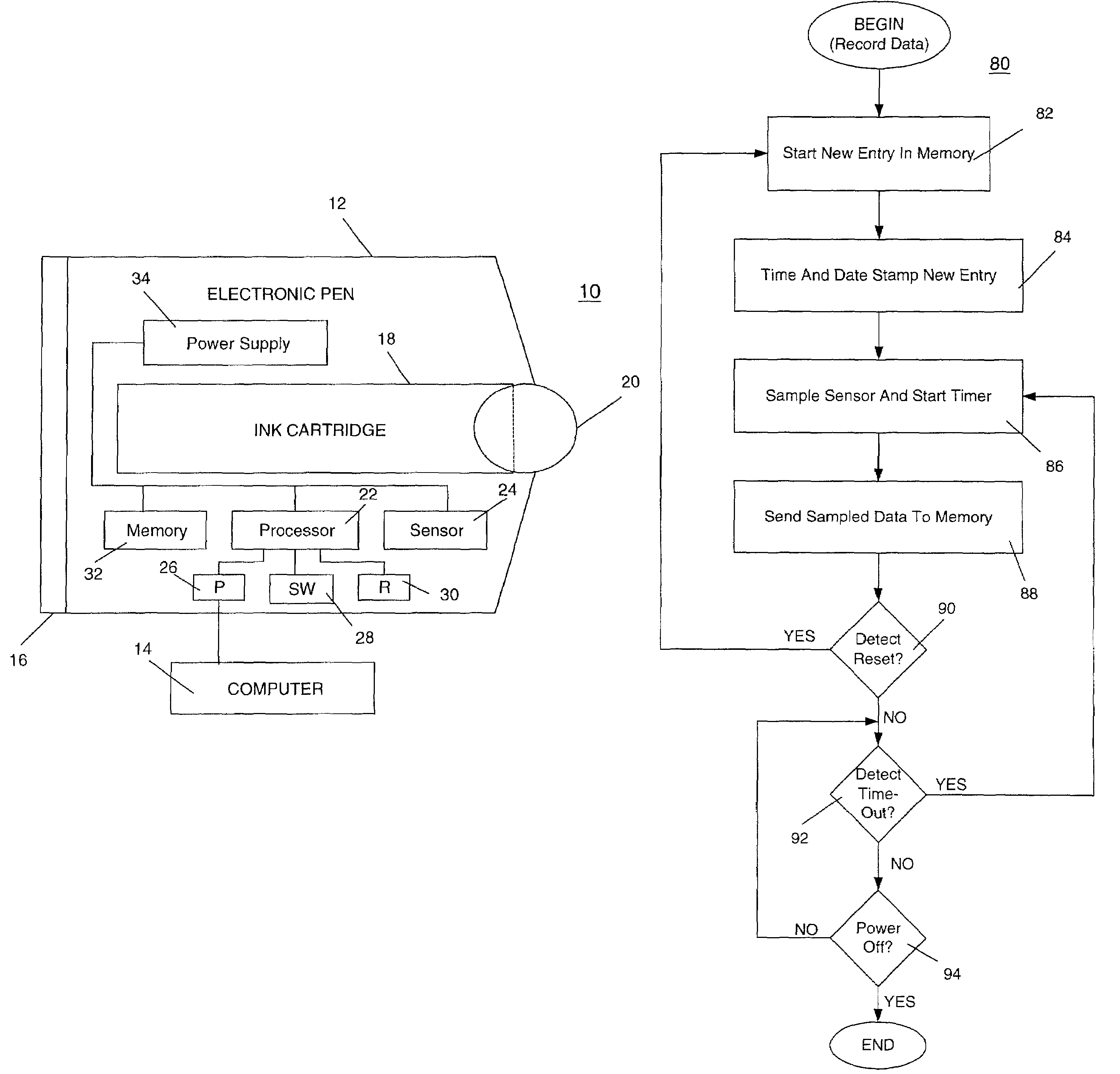
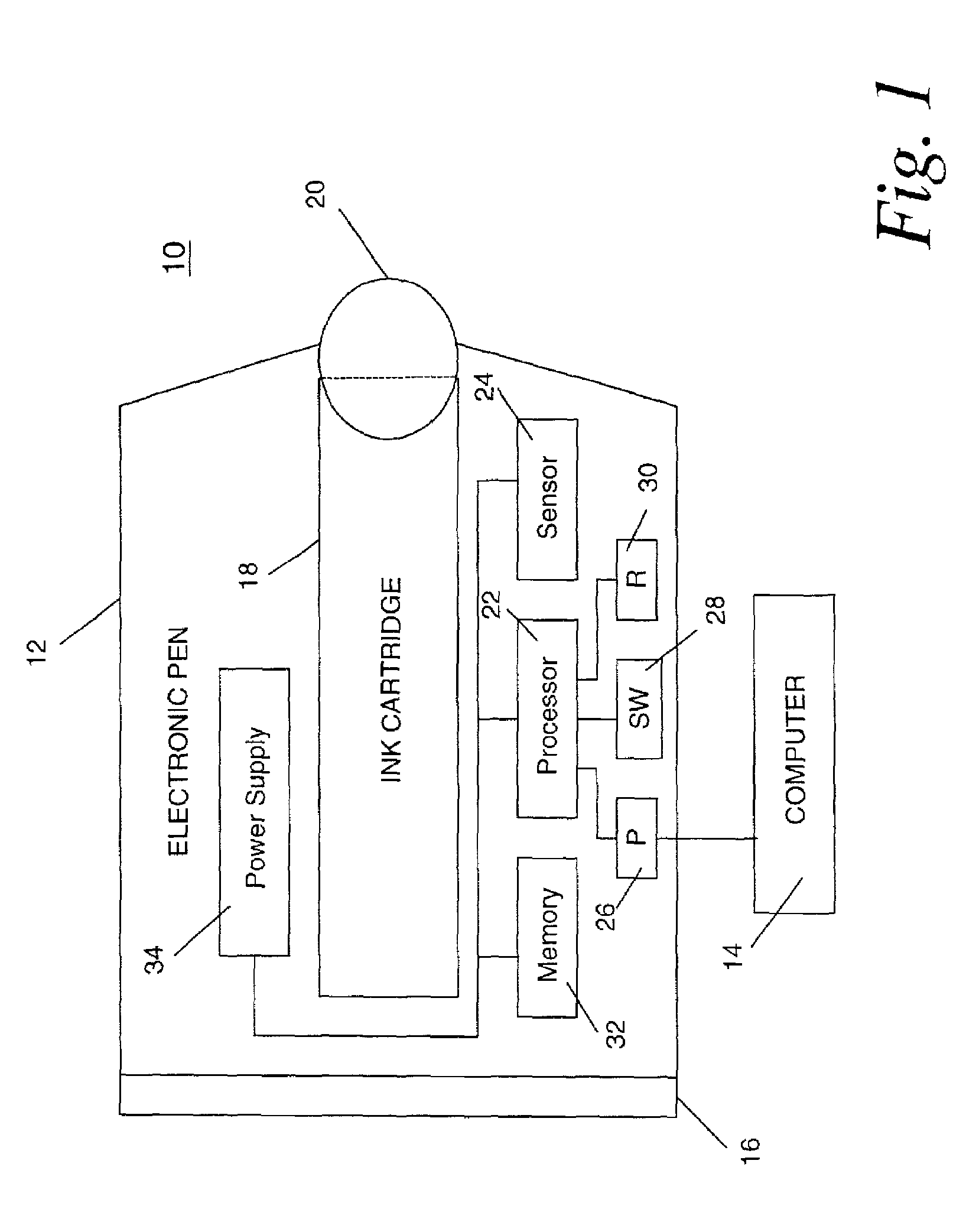
[0011]FIG. 1 is a diagram of an exemplary electronic pen 10 consistent with the present invention. Electronic pen 10 includes a pen body 12 with a cap 16. Cap 16 is typically removable such as through threading in order to access the interior of pen body 12. Pen body 12 contains a conventional ink cartridge 18 for applying ink to a ball point 20. Electronic pen 10 thus may function as a typical ink ball point pen. In addition, electronic pen 10 includes circuitry for detecting motion of ball point 20 and recording data representing that motion. A processor 22 is connected with a sensor 24, which detects motion of ball point 20 and transmits corresponding electronic signals to processor 22. Based upon the electronic signals, processor 22 records corresponding motion data in a memory 32. A power supply 34, such as batteries, provide power to memory 32, processor 22, and sensor 24. By using certain types of memories to implement memory 32, such as an atomic resolution storage (ARS) mem...


PUM


Abstract

An electronic pen for recording motion data relating to use of the pen. It includes a pen body and a ball mounted in the pen body. A sensor in the pen body, located proximate the ball, detects motion of the ball and converts the motion into corresponding electronic signals. A memory in the pen body, electronically coupled to the sensor, receives the electronic signals and stores corresponding data related to the motion. Use of a high-density memory, such as an atomic resolution storage memory, permits recording sufficient data for the motion within a memory module small enough to fit within the pen body.

Description

FIELD OF THE INVENTION[0001]The present invention relates to an electronic pen for recording motion data.BACKGROUND OF THE INVENTION[0002]Electronic pens are known in the art and typically include a pen with a corresponding tablet or a pen with a tether cable connecting it to a computer or computing device. A user may put paper or another medium on the tablet and the motion of the pen as the user writes on the paper is detected by the tablet. The tablet electronically stores the motion data. These types of systems, however, require use of a specialized tablet for detecting motion of the pen or a tether connecting the pen to a computer or computing device. Also, the pens alone typically have limited memory capability and are thus dependent upon the specialized tablet or the tethered computer for the memory needed to capture motion data desired. Accordingly, a need exists for an improved electronic pen.SUMMARY OF THE INVENTION[0003]An electronic pen consistent with the present inventi...

Claims


Application Information

Patent Timeline
IPC IPC(8): G09G5/08G06F3/033
CPCG06F3/03546
Inventor MOREHOUSE, CHARLES C.
Owner HTC CORP
Why Eureka
Try Eureka