Control unit and method for producing the same

a technology of control unit and control box, which is applied in the direction of electrical apparatus casing/cabinet/drawer, hermetically sealed casing, and connection of coupling device, etc., can solve the problem that the conductive track injected in the plastic cannot be completely sealed, and the distance between the connection and/or conductive track is relatively grea

Inactive Publication Date: 2007-03-20
ROBERT BOSCH GMBH
View PDF6 Cites 23 Cited by
  • Summary
  • Abstract
  • Description
  • Claims
  • Application Information

AI Technical Summary

Benefits of technology

[0010]Compared to the known means of achieving the object of the inventions, the control unit according to the present invention having the features of Claim 1, and the corresponding procedure for manufacturing the same, according to Claim 8, have the advantage that a control unit is created that is completely hermetically sealed while ensuring that the circuit located in the housing is contacted to the outside in a simple manner, whereby a large number of contacts can be easily provided.
[0011]Furthermore, the contacts can have a small grid pattern, which reduces the amount of installation space required, and they can be located relatively at random. In addition, the control unit according to the present invention can be manufactured in a simple and, therefore, economical manner.
[0012]According to the idea on which the present invention is based, a sealing gel is provided in a recess in the frame of the control unit, the sealing gel having a viscosity such that it can flow around the electrical conductive tracks that pass through the recess and around a shaped section of a cover that is inserted in the recess.
[0013]It is therefore ensured by way of a single seal that each conductive track is sealed individually and a seal is provided between the base plate and the cover of the control unit. The geometric configuration of the individual conductive tracks is inconsequential, so that when a pressed screen is used for the conductive tracks, for example, folds, constrictions, etc. on the punched edges do not affect the sealing behavior. Furthermore, no particular geometric accuracy of the conductive tracks and / or the grid pattern between the conductive tracks is required. Simple, economical manufacture is therefore possible.
[0014]Since the conductive tracks can be present in any number and in any pattern of distribution on and / or in the housing frame, it is easier to adapt to the requirements of the circuit layout and / or the surrounding structural conditions.
[0022]The conductive tracks are configured as pressed-screen conductive tracks or as flexible-foil conductive tracks in particular. Another configuration of the conductive track is also feasible, however, since the viscous sealing gel can flow around any geometric shape.
[0023]According to another preferred further development, the control unit is pressed onto the associated surface by way of a spring device. This surface can be the carrier surface of a transmission housing or a cooling surface having a different configuration. This application of force creates hydrostatic pressure in the sealing gel, which markedly improves the sealing property. Furthermore, the entire structure of the control unit is held together by the action of force.
[0021]The base plate is composed, particularly advantageously, of a material having good thermal conductivity, e.g., metal. Good heat dissipation to a cooling surface connected with the base plate is therefore ensured.
[0023]According to another preferred further development, the control unit is pressed onto the associated surface by way of a spring device. This surface can be the carrier surface of a transmission housing or a cooling surface having a different configuration. This application of force creates hydrostatic pressure in the sealing gel, which markedly improves the sealing property. Furthermore, the entire structure of the control unit is held together by the action of force.

Problems solved by technology

A disadvantage of the known procedure described above is the fact that the conductive tracks injected in the plastic cannot be sealed completely.
Both means of achieving the object of the inventions have the disadvantage, however, that they can be realized technically and are economically practical only when a few connecting lines and / or conductive tracks are required and the distances between the connections and / or conductive tracks are relatively great.

Method used


Image

  • Control unit and method for producing the same
  • Control unit and method for producing the same
  • Control unit and method for producing the same

Examples


Embodiment Construction

[0037]In the figures, the same reference numerals are used to label components that are the same or that perform the same function.

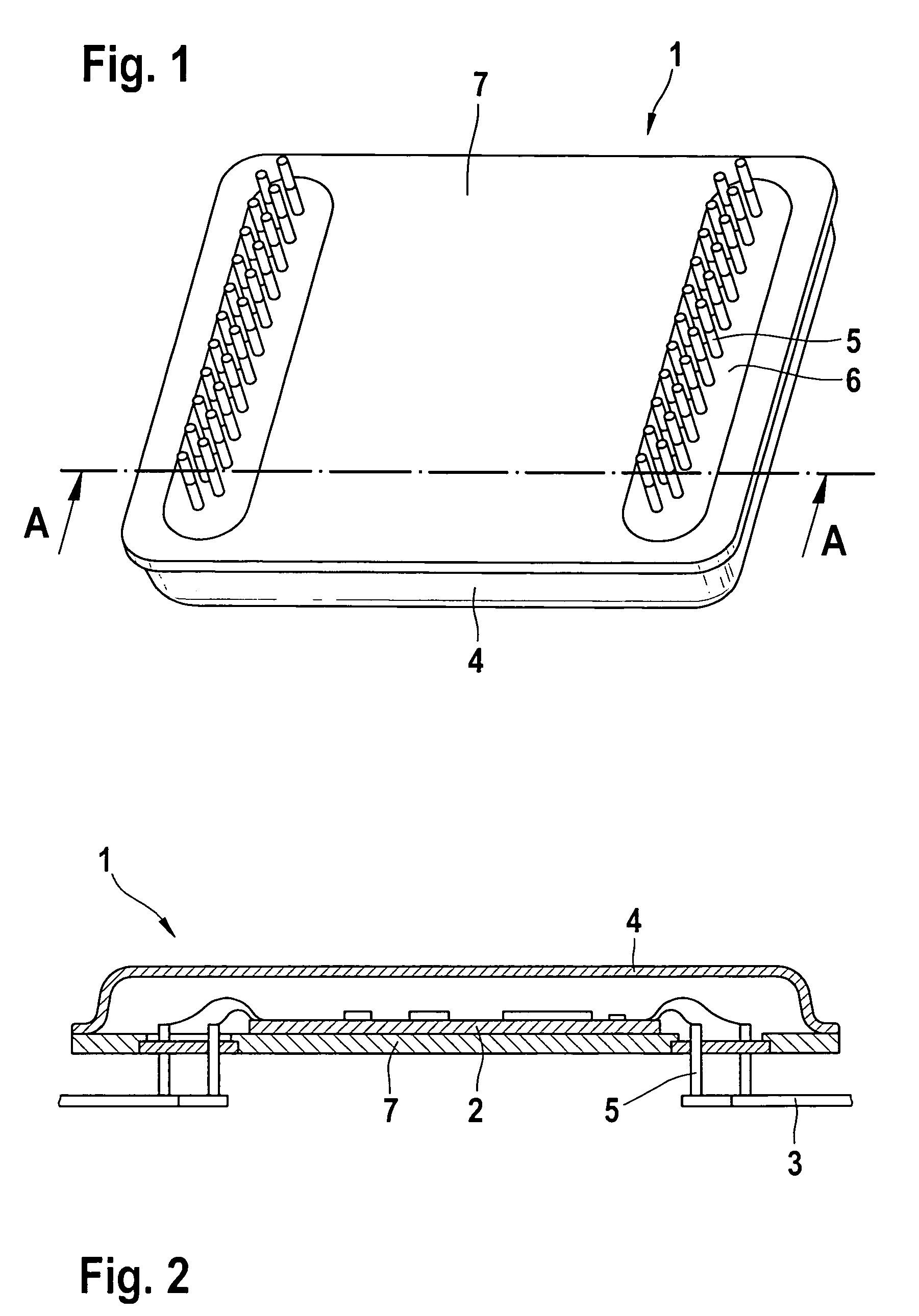
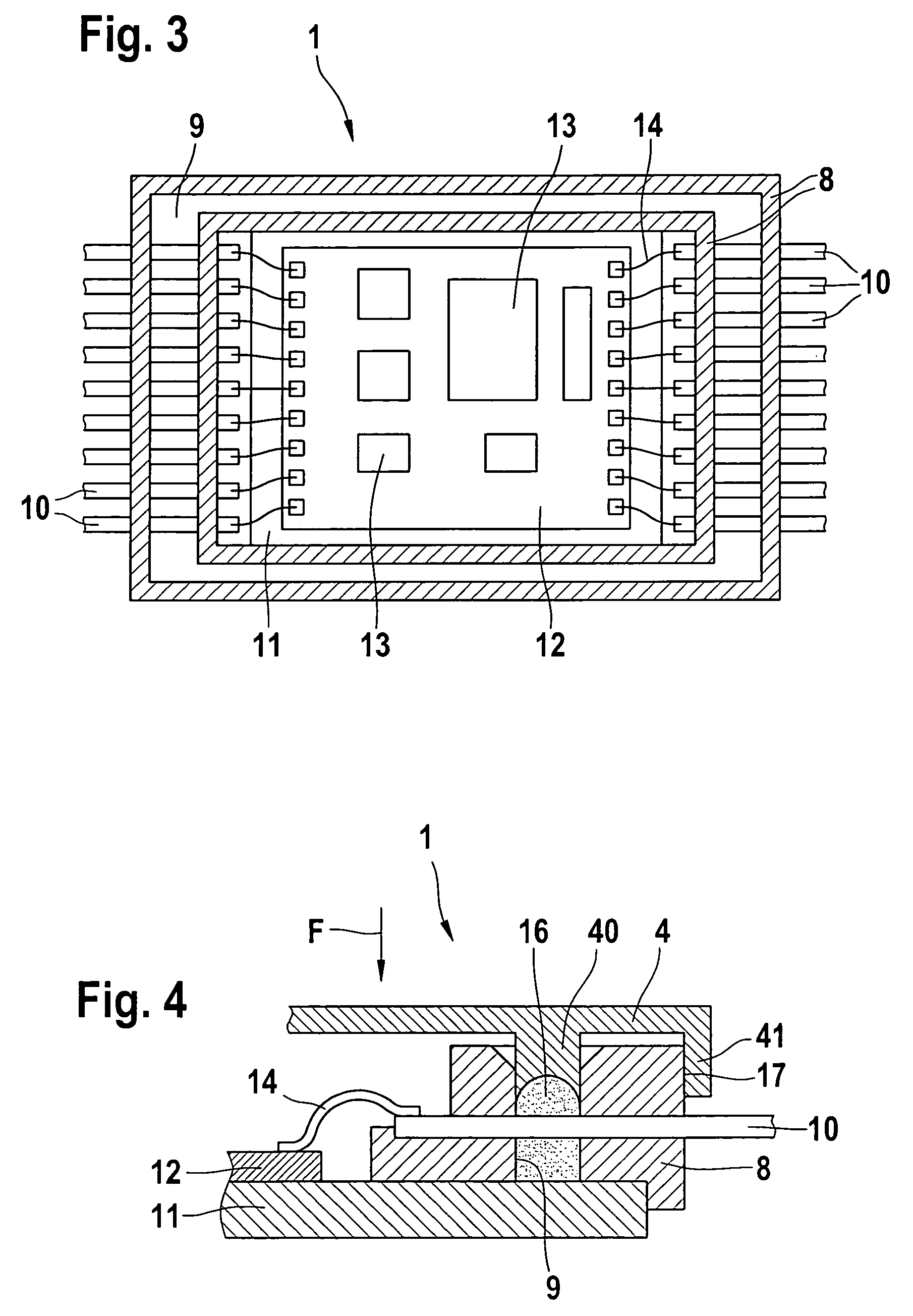
[0038]FIG. 3 shows a top view of a control unit 1 with the cover removed according to a first exemplary embodiment of the present invention. Control unit 1 includes a frame 8 that is preferably made of plastic and includes a circumferential groove 9.

[0039]Conductive tracks 10 are preferably injected into plastic frame 8 and extend through groove 9. Conductive tracks 10 can be configured as pressed-screen conductive tracks or as flexible-foil conductive tracks.

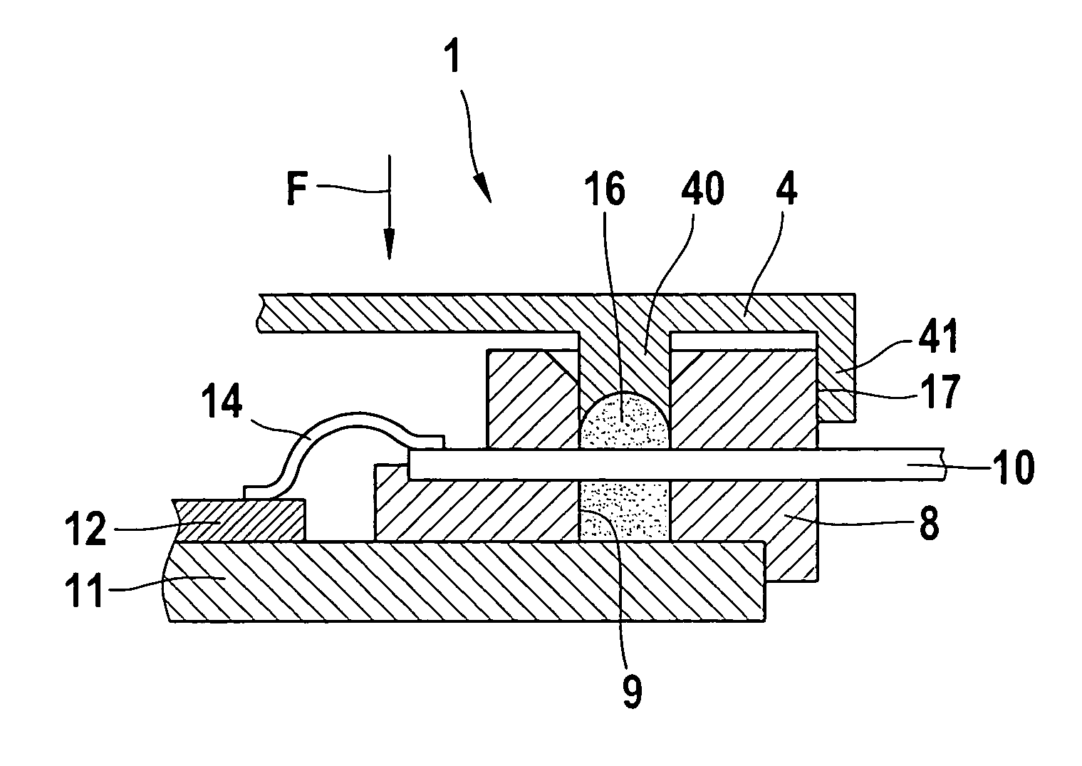
[0040]Control unit 1 further includes a base plate 11 that is preferably made of a material with good heat-conducting properties. Base plate 11 can be made of metal, for example. A circuit carrier 12, e.g., an LTCC or a hybrid, is located on base plate 11, the circuit carrier being equipped with electronic components 13. Circuit carrier 12 is contacted electrically with conductive tracks 10 preferab...


PUM


Abstract

The present invention relates to a control unit (1), for automotive applications in particular, with: a frame (8) that includes a recess (9) across which electrical conductive tracks (10) extend to supply electrical power; a base plate (11) that is inserted in the frame (8); a circuit carrier (12) on which electronic components are mounted and which is installed on the base plate (11); an electrical connection (14) for connecting the circuit carrier (12) with the conductive tracks (10); and a cover (4) for hermetically sealing the control unit (1), the cover including a shaped section that is insertable in the associated recess (9) in the frame (8); whereby a sealing gel (16) is provided in recess (9) with a viscosity such that the sealing gel (16) can flow around the electrical conductive tracks (10) that extend across the recess (9). The present invention further relates to a manufacturing method for manufacturing a control unit (1) of this type.

Description

BACKGROUND INFORMATION[0001]The present invention relates to a control unit, for automotive applications in particular, according to the definition of the species in Claim 1, and a method for manufacturing the control unit.[0002]In automotive applications in particular, control units are subjected to strong mechanical loads due to vibratory stresses.[0003]Control units are used in automotive applications for transmission-shift control, for example. A control unit according to the related art is described below with reference to FIGS. 1 and 2. FIG. 1 shows an underside view of a conventional control unit, and FIG. 2 shows a lateral cross-sectional view of the conventional control unit along the line A—A in FIG. 1.[0004]Control unit 1 contains, for example, a hybrid control unit 2, sensors and at least one plug-in connector for connection to a vehicle wiring harness and / or a transmission connector. The electrical connection between hybrid control unit 2, the sensors and the transmissi...

Claims


Application Information

Patent Timeline
Patent Type & Authority Patents(United States)
IPC IPC(8): H05K7/20B60R16/02B60R16/023H01L21/50H01L23/04H01L23/047H01L23/10H05K5/00H05K5/06
CPCB60R16/0239H01L21/50H05K5/069H05K5/061H05K5/0082H01L23/04H01L23/047H01L23/10H01L24/49H01L24/48H01L2924/19041H01L2924/16152H01L2224/48091H01L2224/4823H01L2224/48472H01L2224/49171H01L2924/09701H01L2924/15312H01L2924/00014H01L2924/00H01L2224/05554H01L2924/10161H01L2924/12042H01L2924/16315H01L2924/181H01L2224/45099H01L2224/45015H01L2924/207B60R16/00B60R16/02H05K5/00
Inventor WETZEL, GERHARD
Owner ROBERT BOSCH GMBH
Why Eureka
Try Eureka