Method for peak power reduction in multiple carrier communications systems

a communication system and peak power technology, applied in multi-frequency code systems, digital transmission, baseband system details, etc., can solve problems such as rf power amplification, rf signal generation, and signal with high peak-to-average ratios, and achieve the effect of reducing individual carrier bandwidths

Inactive Publication Date: 2007-03-20
INTEL CORP
View PDF6 Cites 16 Cited by
  • Summary
  • Abstract
  • Description
  • Claims
  • Application Information

AI Technical Summary

Benefits of technology

[0019]In yet another aspect, the present invention provides a method for signal peak reduction in a multiple carrier communication system where the individual carriers are produced from input symbols that are filtered to reduce individual carrier bandwidths, offset in frequency, and combined into an output signal. The method comprises predicting the effect of filtering on input symbols for each carrier...

Problems solved by technology

These wireless systems are being placed under increasing performance demands which are taxing the capability of available equipment, especially wireless base station equipment.
The increasing number of wireless users is of course readily apparent and this trend is unlikely to slow due to the convenience of wireless services.
A problem exists, however, with the above multiple carrier generation process.
Signals with high peak-to-average ratios create problems in digital-to-analog conversion, RF signal generation, and RF power amplification.
These high multi-carrier peak-to-average ratios once again cause problems in digital-to-analog conversion, RF...

Method used


Image

  • Method for peak power reduction in multiple carrier communications systems
  • Method for peak power reduction in multiple carrier communications systems
  • Method for peak power reduction in multiple carrier communications systems

Examples


Embodiment Construction

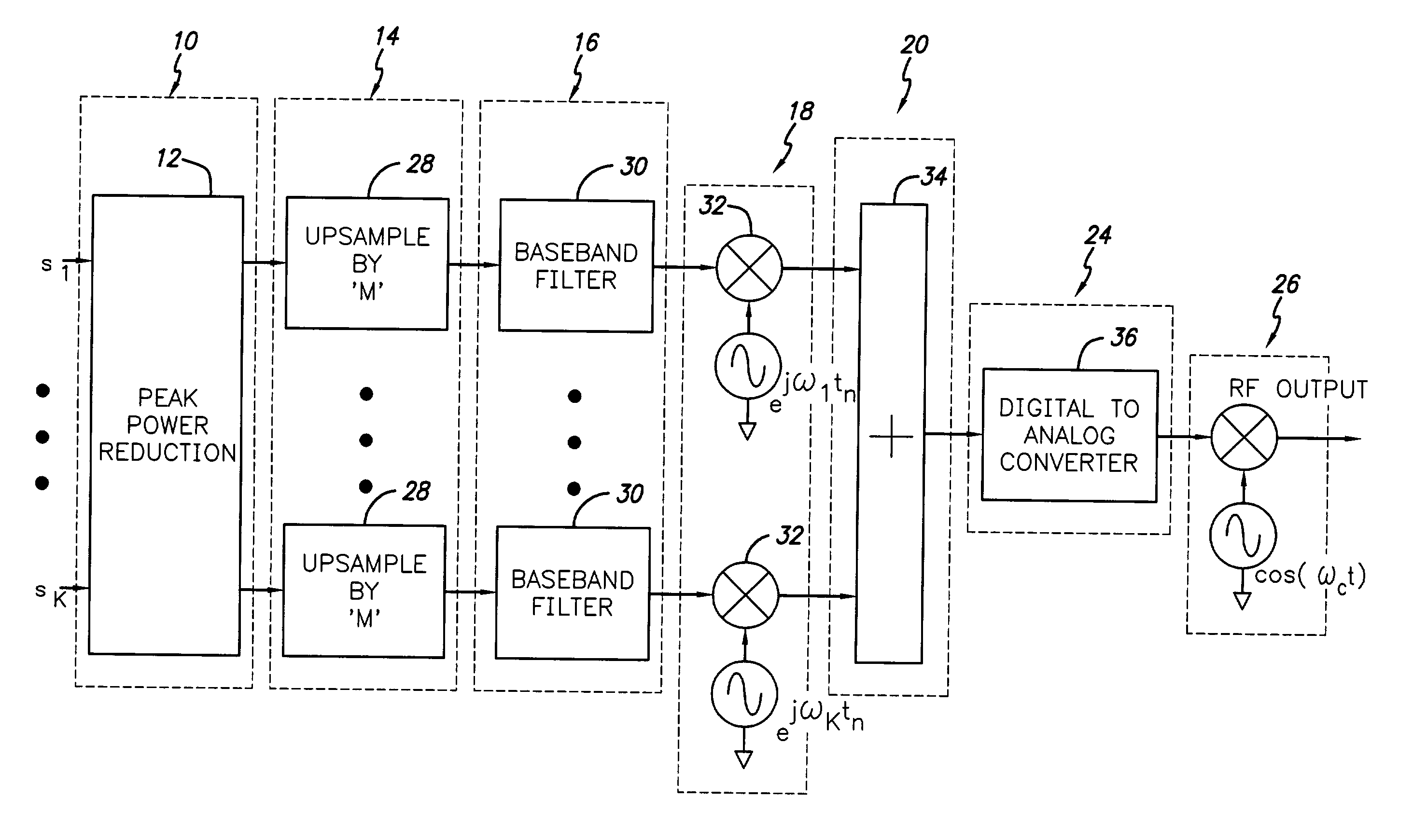
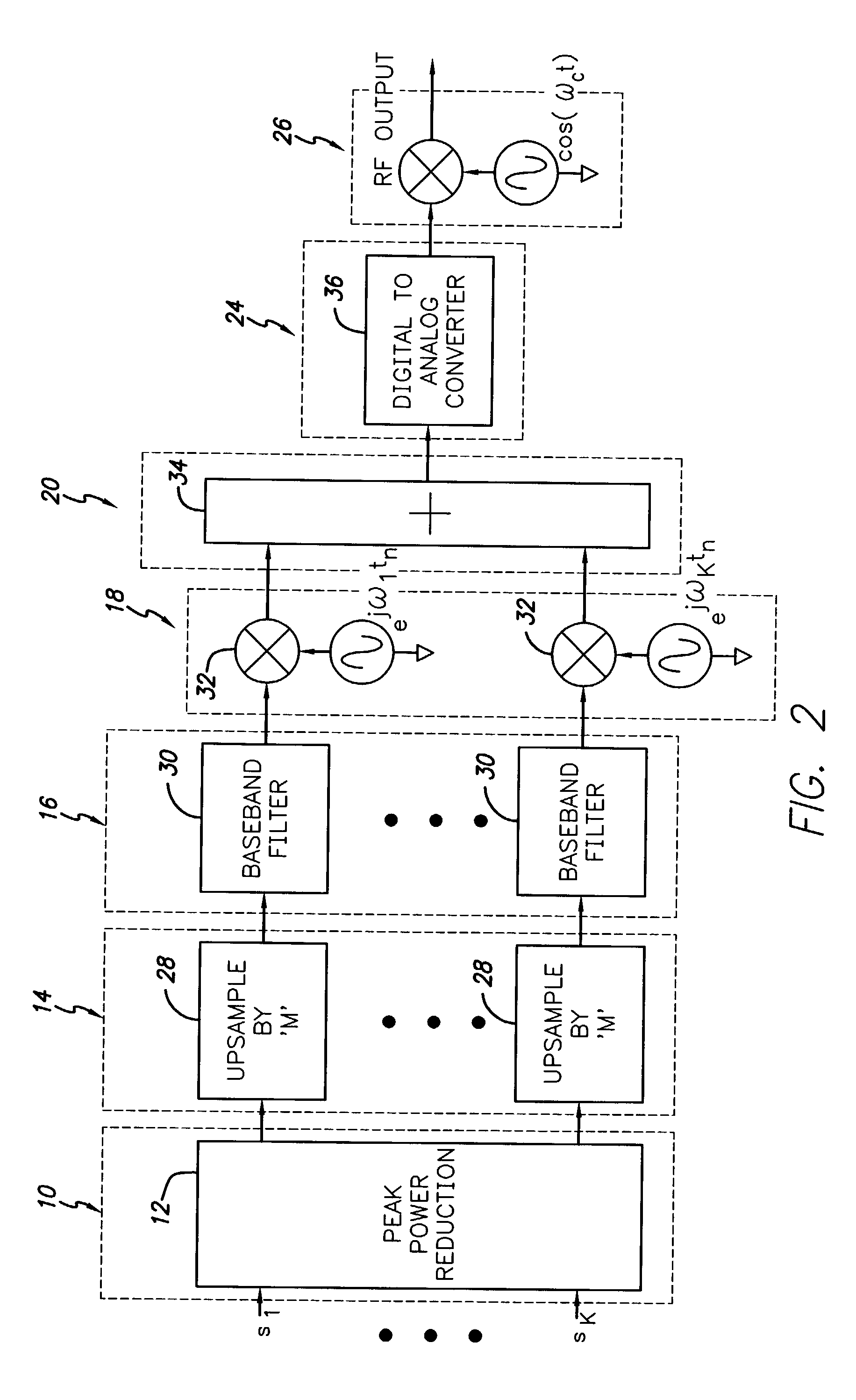
[0055]In FIG. 2 a preferred embodiment of a multiple carrier communication system employing peak power reduction in accordance with the present invention is illustrated. As used herein the term “multiple carrier” or “multi-carrier” refers to the use of two or more frequency offset carriers each of which may have one or more communications channels. For example, each carrier may have plural communication channels using time division multiplexing or code division multiplexing. Each carrier, whether alone or in combination with other carriers, can be used to communicate with one or more receiving stations. One example of such a multiple carrier communication system is a cellular communication system employing multiple frequency offset RF carriers, and multiple user channels may be provided for each carrier in WCDMA (Wide Code Division Multiple Access) or TDMA (Time Division Multiple Access) systems. Other multiple carrier communications systems may also employ the present invention. Fo...


PUM


Abstract

A system and method for signal peak reduction in a multiple carrier communication system where the individual carriers are produced from input symbols that are filtered to reduce individual carrier bandwidths, offset in frequency, and combined into an output signal. A multiple carrier peak reduction unit is provided which modifies the input carrier symbols so that the combined output signal does not exceed a predetermined peak limit value. The multiple carrier peak reduction unit includes filter predictors that predict the effect of each channel filter on that carriers input symbols by using filter coefficient values corresponding to the impulse response function of each filter. The filter predictor outputs are then phase shifted, in correspondence to frequency offsets provided for in multiple carrier signal generation, and combined to produce a prediction of the combined signal output which is then processed to determine the corrections required to the individual channel symbol inputs.

Description

RELATED APPLICATION INFORMATION[0001]The present application is a continuation application of U.S. Ser. No. 09 / 884,302 filed Jun. 19, 2001 now U.S. Pat. No. 6,449,303, which claims priority under 35 USC 19 (e) of provisional application Ser. No. 60 / 212,892 filed Jun. 20, 2000, the disclosure of which is incorporated herein by reference in its entirety.BACKGROUND OF THE INVENTION[0002]1. Field of the Invention[0003]The present invention relates to wireless communications systems, and signal processing apparatus employed in wireless communications systems. More particularly, the present invention relates to communications systems that transmit simultaneously on multiple carriers.[0004]2. Background of the Prior Art and Related Information[0005]Wireless communications systems employing transmission between base stations and remote users are a key component of the modern communications infrastructure. These wireless systems are being placed under increasing performance demands which are...

Claims


Application Information

Patent Timeline
IPC IPC(8): H04K1/10H04K1/02H04L27/28H04B1/707H04L25/03H04L27/26H04L27/36
CPCH04L25/03343H04L27/366H04L27/2614H04B2201/70706H04L27/2621H04L27/2637H04L27/26
Inventor HUNTON, MATTHEW J.
Owner INTEL CORP
Why Eureka
Try Eureka