Electromagnetic induction heat generating roller, heating device, and image forming apparatus

a heat generation roller and induction technology, applied in the direction of electric/magnetic/electromagnetic heating, electrographic process, instruments, etc., can solve the problems of power loss and power loss, and achieve excellent energy efficiency, prevent damage to bearings or the like, and improve heat generation efficiency

Inactive Publication Date: 2007-03-20
PANASONIC CORP
View PDF31 Cites 23 Cited by
  • Summary
  • Abstract
  • Description
  • Claims
  • Application Information

AI Technical Summary

Benefits of technology

[0011]It is an object of the present invention to solve the problems with the conventional technique and to provide a heat generating roller for use in an induction heating method that achieves an improvement in heat generation efficiency and allows damage to bearings or the like to be prevented, a heating device using the heat generating roller, and a heating device of the belt heating type also utilizing electromagnetic induction. Further, another object of the present invention is to provide an image forming apparatus that achieves excellent energy efficiency and allows problems occurring in bearings to be reduced.
[0014]Furthermore, a second heating device according to the present invention includes an electromagnetic induction heat generating belt having an induction heat generating layer, a supporting roller that is composed of a core material and a heat insulating layer provided on an outer side of the core material and makes contact internally with the electromagnetic induction heat generating belt so that the electromagnetic induction heat generating belt is supported rotatably, a pressing roller that makes contact externally with the electromagnetic induction heat generating belt so that a nip part is formed between the pressing roller and the electromagnetic induction heat generating belt, and a magnetic field generating unit that is disposed outside the electromagnetic induction heat generating belt and applies a magnetic field to the induction heat generating layer so that the induction heat generating layer generates heat by induction. In the second heating device, a material to be heated introduced into the nip part is conveyed under pressure by the electromagnetic induction heat generating belt and the pressing roller so as to be heated continuously. Further, in the supporting roller, a magnetism shielding layer that prevents entry of magnetic flux into the core material is provided on an outer side of the core material.

Problems solved by technology

That is, in the case of using a metallic material such as iron, aluminum, a stainless material or the like that is in common use for the core material 824 of the heat generating roller 820, the core material 824 itself generates heat by induction heating due to passing of the alternating magnetic fields H, resulting in a loss of power.
Further, the heat generation of the core material 824 leads to the occurrence of problems such as, for example, damage to bearings supporting the core material 824 caused due to a high temperature.
Similarly, in the conventional induction heating fixing device of the belt heating type shown in FIG. 12, the following problems have been presented.
That is, in the case where the inner pressing roller 920 is formed of a metallic material such as iron, aluminum, a stainless material or the like, a high-frequency magnetic field generated by the coil assembly 960 reaches the inner pressing roller 920, so that the inner pressing roller 920 generates heat, resulting in a loss of power.
Further, the heat generation of the inner pressing roller 920 leads to the occurrence of problems such as, for example, damage to bearings supporting the inner pressing roller 920 caused due to a high temperature.

Method used


Image

  • Electromagnetic induction heat generating roller, heating device, and image forming apparatus
  • Electromagnetic induction heat generating roller, heating device, and image forming apparatus
  • Electromagnetic induction heat generating roller, heating device, and image forming apparatus

Examples


embodiment 1

[0054

[0055]FIG. 5 is a cross sectional view of an image forming apparatus using a heating device according to an embodiment of the present invention as a fixing device. The heating device according to this embodiment is an electromagnetic induction heating device of the roller heating type. The following description is directed to the configuration and operation of this device.

[0056]Reference numeral 1 denotes an electrophotographic photoreceptor (hereinafter, referred to as a “photosensitive drum”). The photosensitive drum 1, while being driven to rotate at a predetermined peripheral velocity in a direction indicated by an arrow, has its surface charged uniformly to a predetermined potential by a charger 2. Reference numeral 3 denotes a laser beam scanner that outputs a laser beam modulated in accordance with a time-series electric digital pixel signal of image information input from a host device such as an image reading apparatus, a computer or the like, which is not shown in the...

embodiment 2

[0085

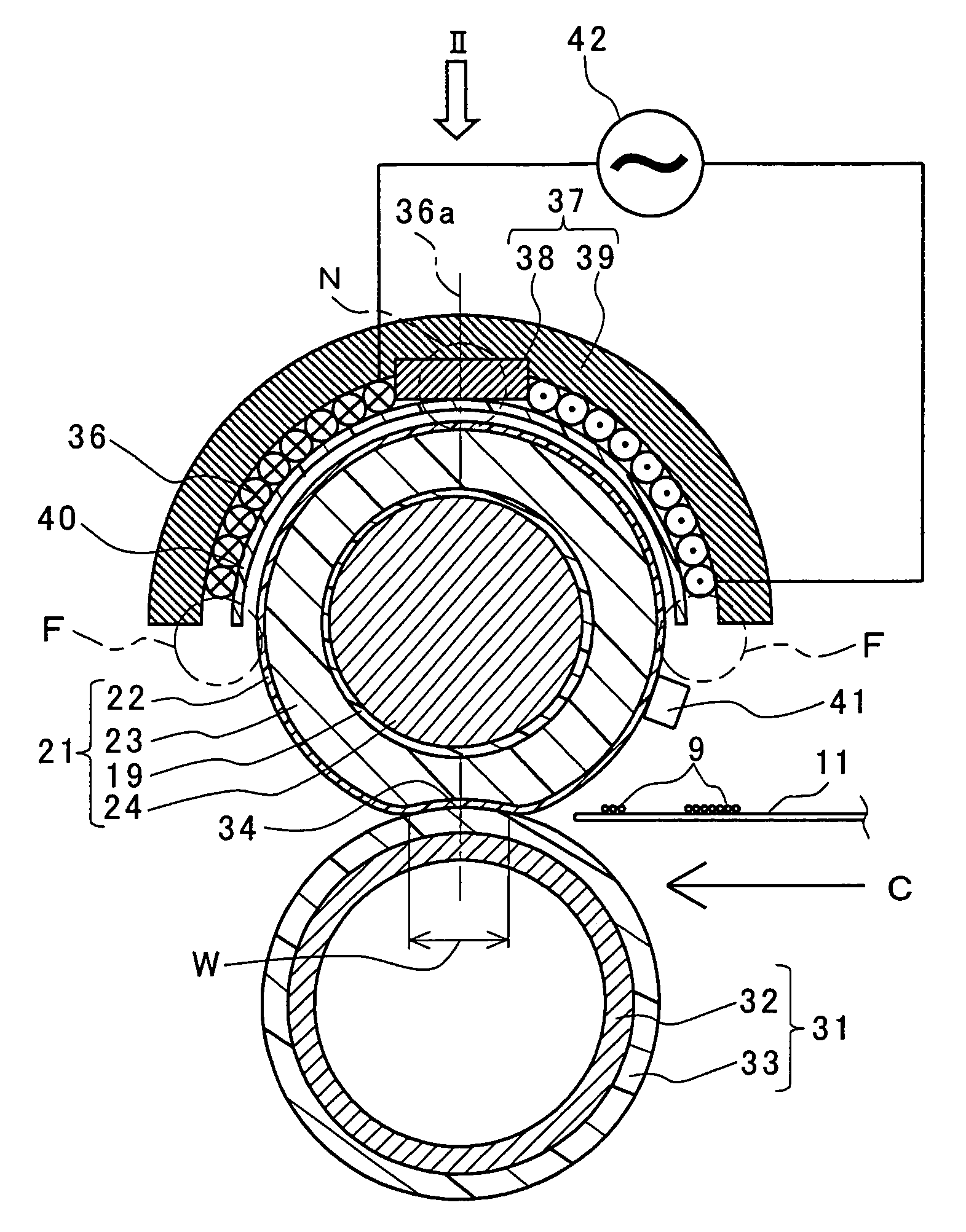
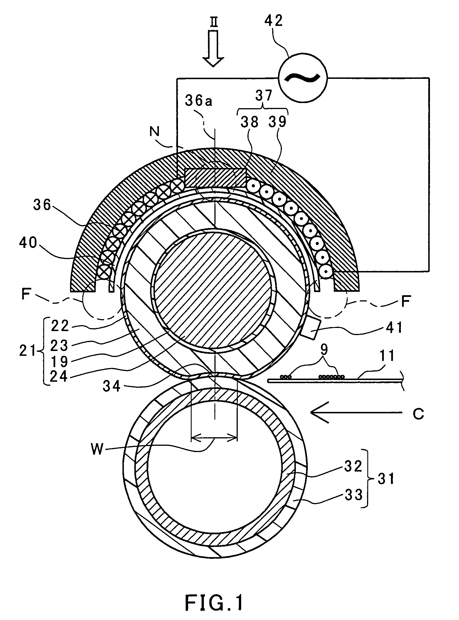
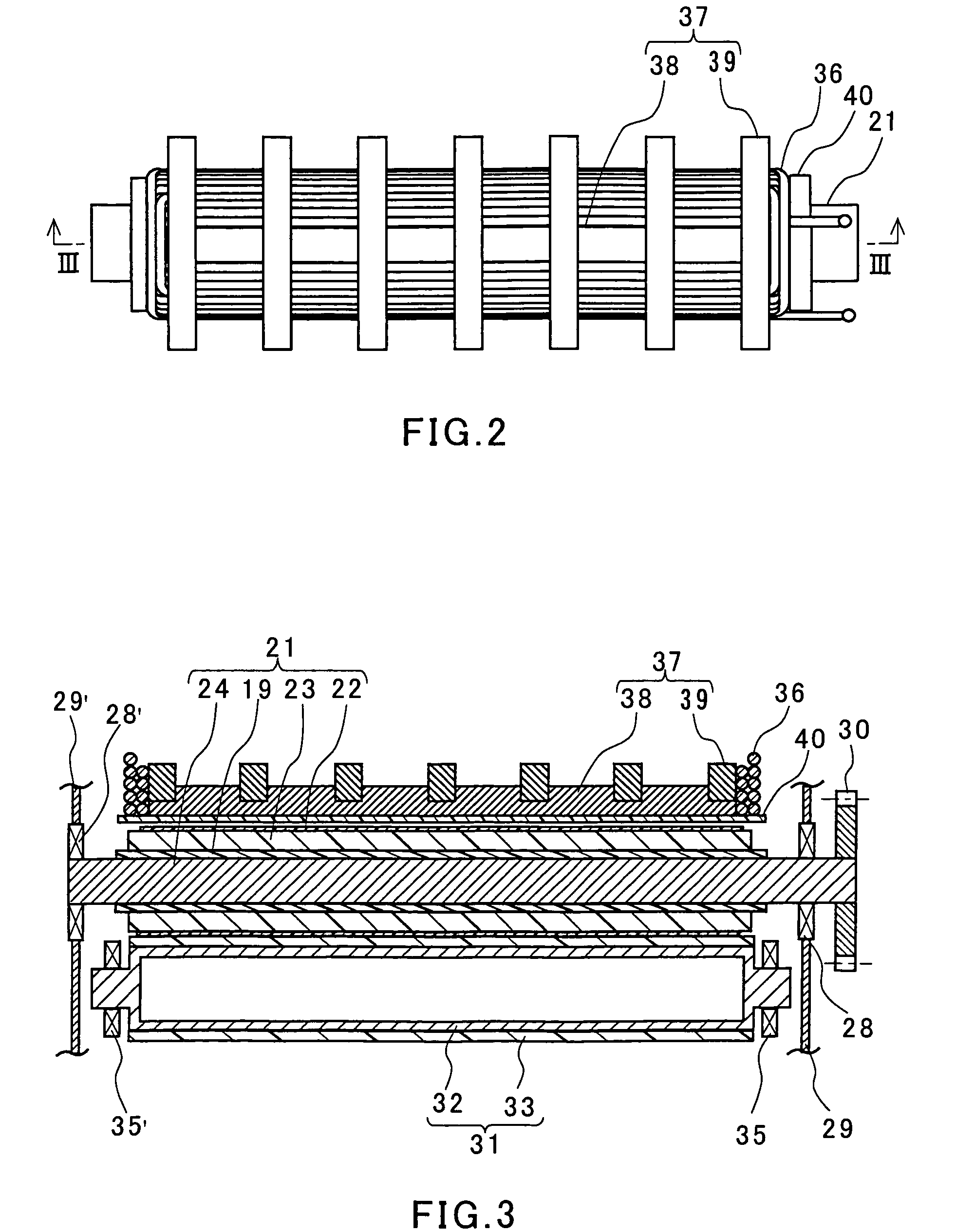
[0086]The only difference between Embodiment 2 and Embodiment 1 lies in the configuration of the electromagnetic induction heat generating roller 21. FIG. 6A is a cross sectional view of an electromagnetic induction heat generating roller according to Embodiment 2 of the present invention that is used in the image forming apparatus shown in FIG. 5. FIG. 6B is an expanded sectional view of a portion 6B shown in FIG. 6A. In FIGS. 6A and 6B, like reference characters indicate like members that have the same functions as those described with regard to Embodiment 1, for which detailed descriptions are omitted.

[0087]A heat generating roller 21 according to this embodiment includes a core material 24, an elastic layer 23, a heat generating layer 22, a second elastic layer 26, and a mold releasing layer 27, which are provided outwardly in this order. As in the case of Embodiment 1, the core material 24 is formed of a non-magnetic stainless material. Unlike the case of Embodiment 1, the...

embodiment 3

[0090

[0091]The only difference between Embodiment 3 and Embodiment 1 lies in the configuration of the magnetism shielding layer of the electromagnetic induction heat generating roller 21. FIG. 7A is a schematic perspective view of a core material 24 of an electromagnetic induction heat generating roller according to Embodiment 3 of the present invention. The core material 24 includes a magnetism shielding layer.

[0092]In this embodiment, the magnetism shielding layer is formed by using a ring (hollow cylindrical member) 51 shown in FIG. 7B and is composed of a plurality of the rings 51. The plurality of the rings 51 are fitted externally around the core material 24 and fixed thereto. The ring 51 contains a magnetic material such as ferrite. It is preferable that the adjacent rings 51 are joined to each other. However, the adjacent rings 51 also may be spaced slightly from each other.

[0093]In place of the ring 51, an arc-shaped member 52 shown in FIG. 7C may be attached to an outer su...


PUM


Abstract

An electromagnetic induced heating roller comprises a core member, an elastic layer, induction heating layer, and a mold release layer in this order from inside to outside. Further, a magnetic shield layer for preventing a magnetic flux from penetrating into the core member is interposed between the induction heating layer and the core member. The production of an alternating magnetic field from a magnetic field generating device, a leakage flux having penetrated through the induction heating layer is trapped by the magnetic shield layer. As a result, most of the impressed alternating magnetic flux is consumed for heating the heating layer, resulting in an improvement in the heating efficiency. A trouble is prevented which is generated by heating the bearing of the core member.

Description

[0001]This application is a Continuation-in-Part of U.S. patent application Ser. No. 10 / 480,344 filed Dec. 9, 2003 now abandoned, which is a National Stage of PCT / JP02 / 11328 filed on Oct. 31, 2002.TECHNICAL FIELD[0002]The present invention relates to an electromagnetic induction heat generating roller that generates heat by electromagnetic induction heating for heating a sheet-like material to be heated by making continuous contact with the material to be heated. Further, this invention relates to a heating device for fixing a toner image on a recording material by heating in an image forming apparatus that forms an image using toner by an electrophotographic method or another similar method that is used for copiers, printers and the like. Moreover, this invention relates to an image forming apparatus including such a heating device as a fixing device.BACKGROUND ART[0003]Description will be made by using as an example a fixing device (heating device) in an image forming apparatus su...

Claims


Application Information

Patent Timeline
Patent Type & Authority Patents(United States)
IPC IPC(8): G03G15/20H05B6/14
CPCG03G15/2053G03G15/2057H05B6/145G03G2215/2029G03G2215/2032G03G2215/2016
Inventor KATAKABE, NOBORUIMAI, MASARUFUJIMOTO, KEISUKE
Owner PANASONIC CORP
Why Eureka
Try Eureka