Dispensing valve

a valve and valve body technology, applied in the field of valve assemblies, can solve the problems of only being used, unable to meet the needs of users, and unnecessarily increasing the cost of the dispenser, so as to achieve cleaner and more reliable operation, less likelihood of clogging, and convenient manufacturing and assembly.

Inactive Publication Date: 2007-03-27
SC JOHNSON & SON INC
View PDF37 Cites 44 Cited by
  • Summary
  • Abstract
  • Description
  • Claims
  • Application Information

AI Technical Summary

Benefits of technology

[0016]When the diaphragm is in the first configuration the seal can restrict the flow of active chemical out the valve assembly. When the pressure of chemical inside the accumulation chamber exceeds a specified threshold, the diaphragm can move to a second configuration where the active chemical is permitted to spray from the valve assembly.
[0021]The present invention achieves a secure mounting of a valve assembly on an aerosol can, yet provides an actuator that has two modes. In one mode the valve assembly is operationally disconnected from the actuator valve of the aerosol container (a mode suitable for shipment or long-term storage). Another mode operationally links the valve assembly to the aerosol container interior, and begins the cycle of periodic and automatic dispensing of chemical there from. The periodic operation is achieved without requiring the use of electrical power to motivate or control the valve.
[0022]The valve assembly has few parts, and is inexpensive to manufacture and assemble. Moreover the separate accessing of the gas propellant lets the gas (as distinguished from more viscous liquid) motivate the diaphragm and thus provides for cleaner and more reliable operation. By preventing substantial amounts of liquid from entering the propellant passageway, there is much less likelihood for clogging due to extended use over months. Furthermore, the orifice plate enables precise metering of accumulation phase intervals.

Problems solved by technology

While this can be done manually, there are situations where this is inconvenient.
Where electric power is required, the cost of the dispenser can be unnecessarily increased.
Moreover, for some applications power requirements are so high that battery power is impractical.
Where that is the case, the device can only be used where linkage to conventional power sources is possible.
However, some biased diaphragm systems have suffered from reliability problems (e.g. clogging, leakage, uneven delivery).
Moreover, they sometimes do not securely attach to the aerosol can.
Moreover, the cost of some prior intermittent spray control systems makes it impractical to provide them as single use / throw away products.
Over time, this can lead to clogging of the valve, and thus inconsistent operation.
However, this device did not achieve reliable automatic operation.

Method used


Image

  • Dispensing valve
  • Dispensing valve
  • Dispensing valve

Examples


Embodiment Construction

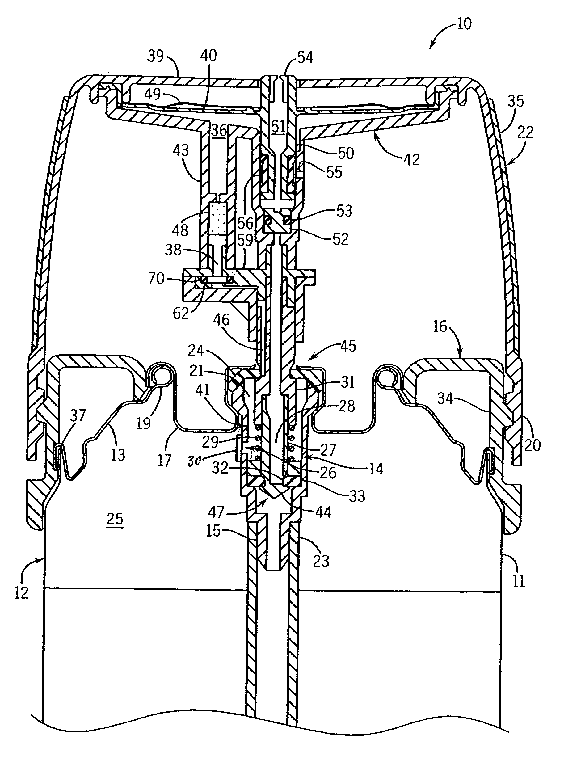
[0039]Referring initially to FIG. 1, an aerosol can 12 includes a cylindrical wall 11 that is closed at its upper margin by a dome 13. The upper margin of the can wall 11 is joined at a can chime 37. An upwardly open cup 17 is located at the center of the dome 13 and is joined to the dome by a rim 19.

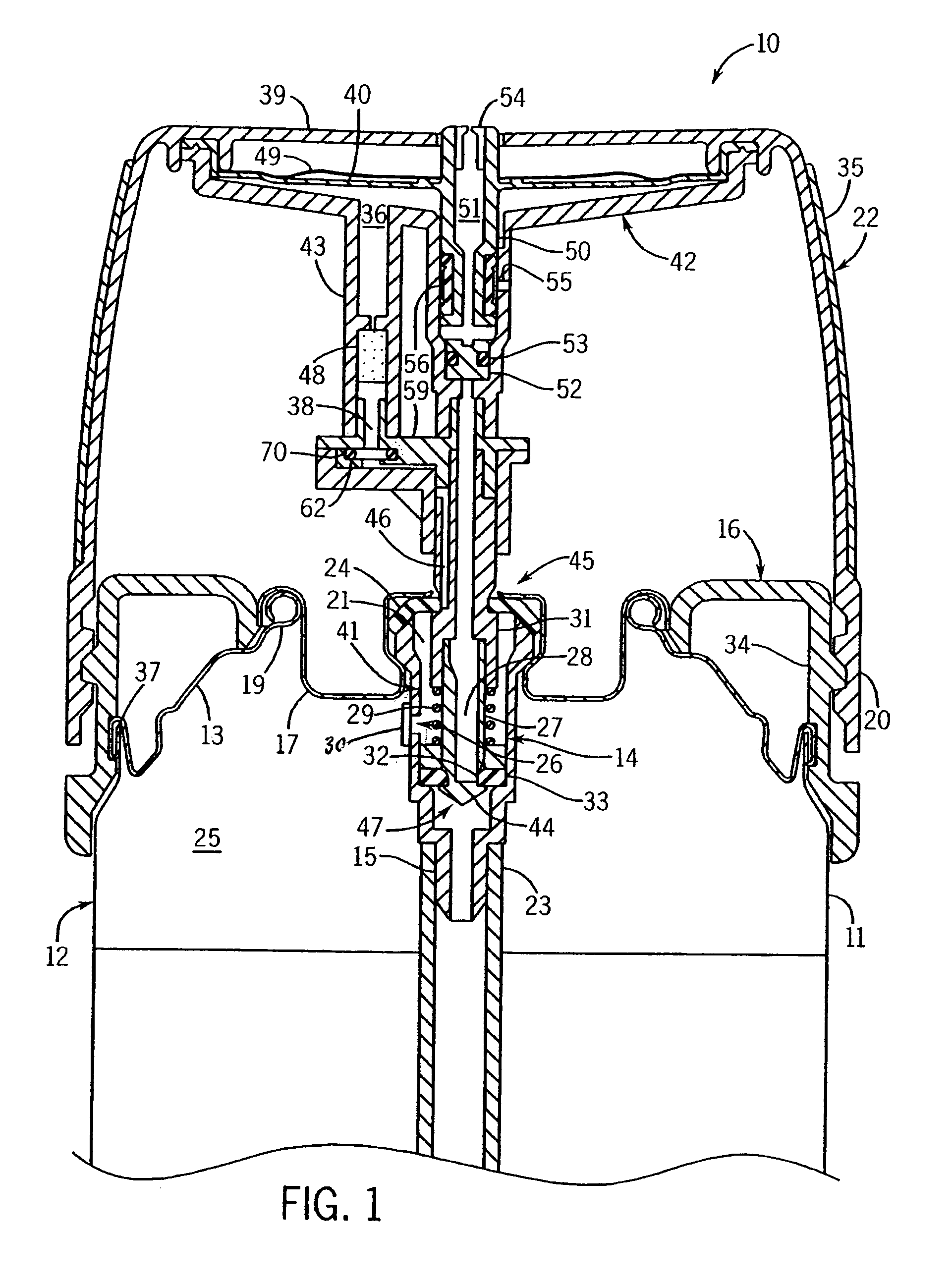
[0040]The can 12 includes an axially extending conduit 23 that is centrally disposed therein, and opens into a mixed pressurized chemical (active and gas propellant) at one end (preferably towards the bottom of the can). The upper region 25 of the can interior above the active chemical line contains pressurized gas propellant. The lower region contains a mix of liquid gas and the active chemical. The upper end of conduit 23 receives a tee 15 that interfaces with the interior of a dispenser 10, through which the chemical may be expelled.

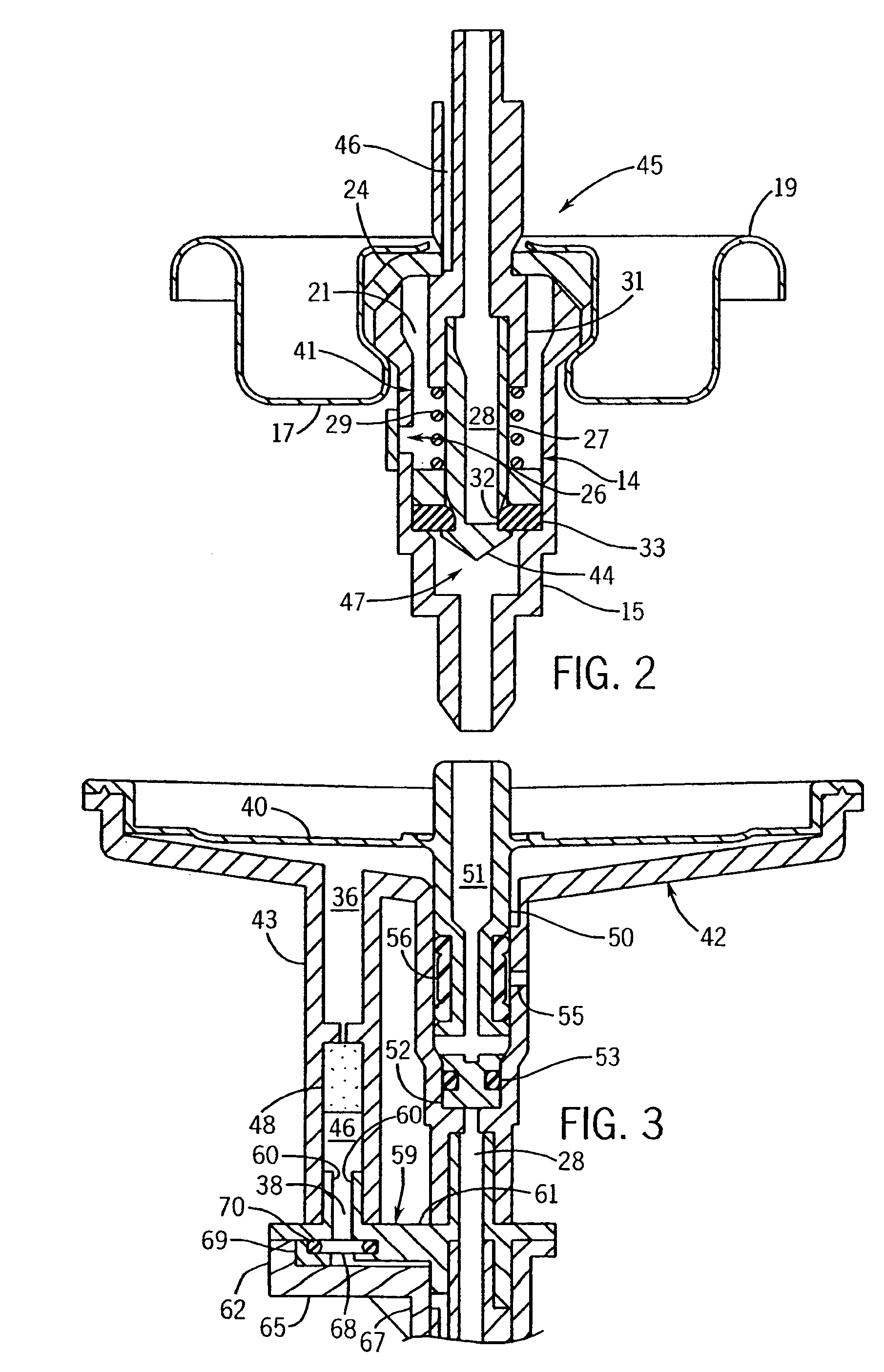
[0041]Dispenser 10 includes a can valve assembly 45 that, in turn, includes a gas propellant valve assembly 41 and an active valve assembly 47. Dispenser...


PUM


Abstract

A valve assembly can automatically dispense aerosol content from an aerosol container at predetermined intervals without the use of electric power. A diaphragm at least partially defines an accumulation chamber that receives gas propellant from a portion of the can during an accumulation phase. Once the internal pressure of the accumulation chamber reaches a predetermined threshold, the diaphragm moves, carrying with it a seal so as to unseal an outlet channel, and thereby initiate a spray burst of the main active chemical. The diaphragm assumes its original position when the pressure within the accumulation chamber falls below a threshold pressure.

Description

CROSS-REFERENCE TO RELATED APPLICATIONS[0001]Not applicableSTATEMENT REGARDING FEDERALLY SPONSORED RESEARCH / DEVELOPMENT[0002]Not applicableBACKGROUND OF THE INVENTION[0003]The present invention relates to aerosol dispensing devices, and in particular to valve assemblies that provide automatic dispensing of aerosol content at predetermined time intervals, without requiring the use of electrical power.[0004]Aerosol cans dispense a variety of ingredients. Typically, an active is mixed with a propellant which inside the can is at least partially in a gas state, but may also be at least partially dissolved into a liquid containing active. Typical propellants are a propane / butane mix or carbon dioxide. The mixture is stored under pressure in the aerosol can. The active mixture is then sprayed by pushing down / sideways on an activator button at the top of the can that controls a release valve.[0005]For purposes of this application, the term “active chemical” is used to mean that portion of ...

Claims


Application Information

Patent Timeline
Patent Type & Authority Patents(United States)
IPC IPC(8): B65D83/14B65D83/16
CPCB65D83/265B65D83/7535B65D83/44B65D83/32
Inventor JAWORSKI, THOMASWESTPHAL, NATHAN R.VARANASI, PADMA P.ROBLING, DARREN K.ADAIR, JOEL E.KUBICEK, CHRIS A.
Owner SC JOHNSON & SON INC
Why Eureka
Try Eureka