Electrical conductive path for a medical electronics device

a technology of electrical conductive path and medical electronics, which is applied in the direction of coupling contact member, coupling device connection, therapy, etc., can solve the problems of large surgical operation with attendant risk factor, large number of discrete electrical impulses, and undesirable setscrews, etc., and achieves very accurate and consistent dimensions.

Active Publication Date: 2007-03-27
BAL SEAL ENG CO INC
View PDF29 Cites 129 Cited by
  • Summary
  • Abstract
  • Description
  • Claims
  • Application Information

AI Technical Summary

Benefits of technology

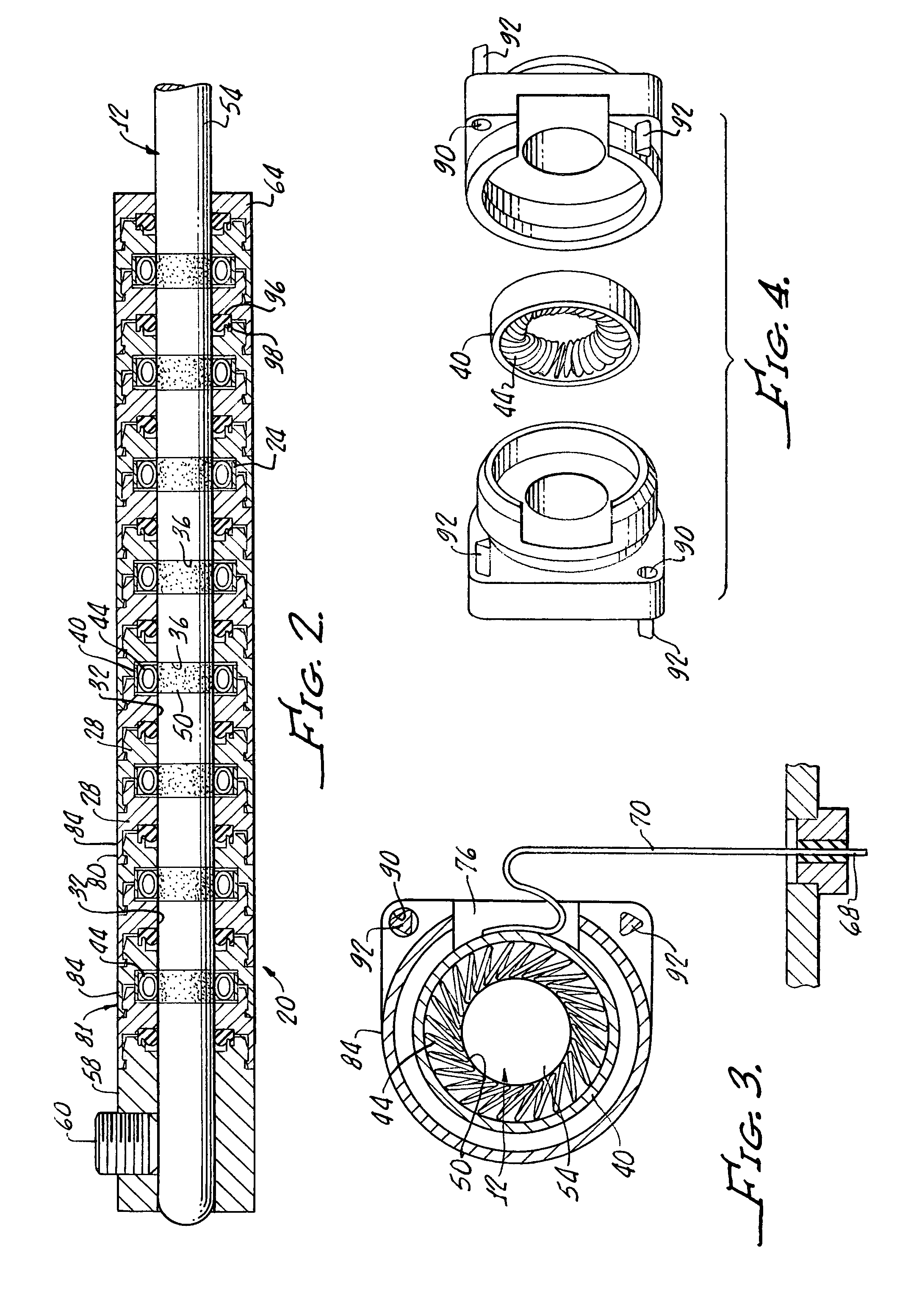
[0007]In current practice, the connector generally consists of a setscrew in a metal connector or some type of spring in a metal housing. Where the spring is used, it provides the conductive path between the metal housing and the contact ring of the lead. Setscrews are very undesirable where large numbers of connectors are required because each connector must be tightened with a torque wrench. A spring retained in a metal housing provides a reliable contact with controlled insertion forces that is convenient for both insertion and removal obviates the requirement for a torque wrench. A canted coil spring has very desirable characteristics for this application since its nearly constant force over a wide range of deflection compensates for any irregularities on the surface of the lead electrical contact rings and the insertion force can be controlled.
[0008]The housings, which can number anywhere from two to twenty-four or even more are now machined from metals such as MP35N, titanium, or even platinum, are significant cost drivers. The present invention utilizes an implantable polymeric biocompatible material housing that can be fabricated by injection molding to reduce the cost of the contacts with an electrical path.SUMMARY OF THE INVENTION
[0011]The spring ring may be cut to size from tubing and thus is dimensionally very accurate and consistent from ring to ring and it may be fabricated from any materials acceptable for implants.

Problems solved by technology

Once the leads are implanted in the body, removal may involve major surgery with an attendant risk factor.
While some applications are very simple requiring only two leads because they only have to transmit two discrete signals to the tissues, others are very complex and require a very large number of discrete electrical impulses.
Setscrews are very undesirable where large numbers of connectors are required because each connector must be tightened with a torque wrench.

Method used


Image

  • Electrical conductive path for a medical electronics device
  • Electrical conductive path for a medical electronics device
  • Electrical conductive path for a medical electronics device

Examples


Embodiment Construction

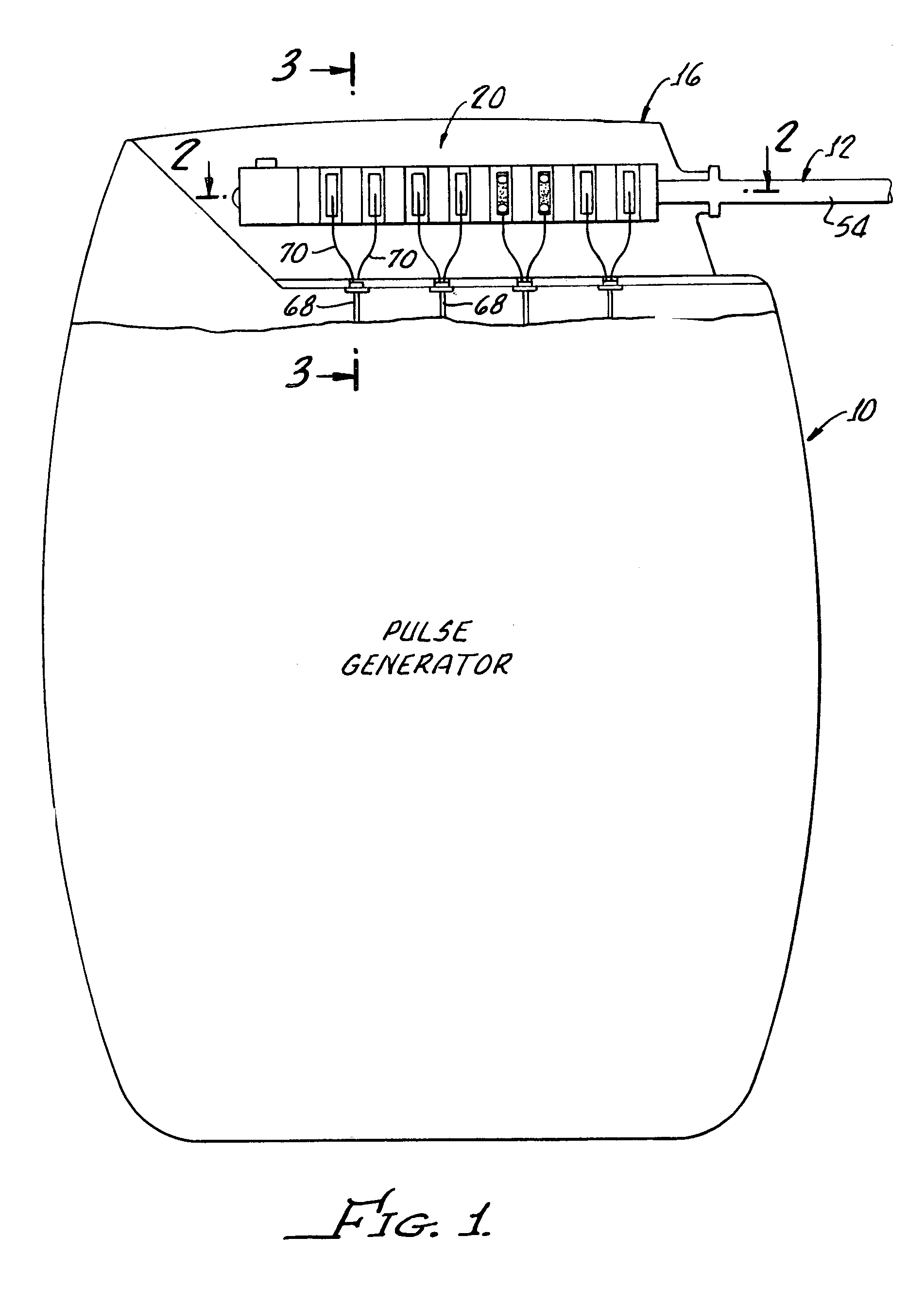
[0026]In general, FIG. 1 shows an implanted medical electronics device pulse generator 10. This device 10 generates electrical impulses that are delivered to target tissue (not shown) by a lead 12 that is also implanted. The pulse generator 10 may also be a receptor and processor of information from the targeted tissues through the implanted leads.

[0027]Devices 10 have a wide range of uses such as cardiac rhythm management, implanted defibrillators, neurostimulaters used for the control of pain, treatment of nervous disorders, incontinence, clinical depression and other applications.

[0028]The fundamental requirements are generally the same for most applications. An electrical signal must be transmitted from the pulse generator 10 to the implanted lead 12 to the targeted tissue. This invention is concerned with the transmission of the impulses signals from the pulse generator 10 to the lead 12.

[0029]A header 16 as shown in FIG. 1 is attached to the pulse generator 10. The header 16 c...


PUM


Abstract

An electrical conductive path for medical electronic device generally includes a plurality of stackable molded non-conductive housing with each housing having a bore therethrough alignable with adjacent housing bores. The adjacent housings and define any combination when stacked, spaced apart slots for receiving a plurality of electrically conductive spring rings. A plurality of electrically conducting garter springs are disposed within corresponding spring rings and a cable is provided including wires attached to corresponding spring rings.

Description

[0001]The present application claims priority from U.S. Ser. No. 60 / 605,275 filed Aug. 26, 2004 which is incorporated herewith in its entirety by this subject reference thereto.[0002]This invention is generally directed to implantable medical devices and is more particularly directed to the electrical conductive path between a pulse generator and the implantable lead or leads.[0003]Implantable medical electronics devices consist of an implanted pulse generator that is used to provide electrical stimulation to certain tissues and an implantable lead or leads that are used to transmit the electrical impulse to the targeted tissues. The first ones were developed for cardiac pacemaking, and that area now has a number of applications for cardiac rhythm management, treatments for congestive heart failure, and implanted defibrillators. Other devices are used for neurostimulation with a wide range of uses such as pain control, nervous tremor mitigation, incontinent treatment, epilepsy seizu...

Claims


Application Information

Patent Timeline
Patent Type & Authority Patents(United States)
IPC IPC(8): H01R13/17
CPCA61N1/3752H01R2201/12
Inventor NAVIAUX, JACQUES
Owner BAL SEAL ENG CO INC
Why Eureka
Try Eureka