High performance support-separators for communications cables

a technology of support and separation, which is applied in the direction of insulated conductors, cables, waveguides, etc., can solve the problems of increased unwanted cross-talk, shielded cables, and undesirable energy transferred between conductor pairs, so as to improve power sum, improve electrical properties, and crush resistance similar

Inactive Publication Date: 2007-03-27
CABLE COMPONENTS GROUP
View PDF10 Cites 23 Cited by
  • Summary
  • Abstract
  • Description
  • Claims
  • Application Information

AI Technical Summary

Benefits of technology

[0029]The various shaped core support-separators of this invention provides a superior crush resistance to the protrusions of the standard “X” or other similar supports. A superior crush resistance is obtained by the arch-like design for the anvil-shaped separators that provide clearance channels for additional support to the outer section of the cable. The various shaped cores better preserves the geometry of the pairs relative to each other and of the pairs relative to the other parts of the cables, such as the possible use of a shield or optical fibers. The anvil-shape provides an exterior surface that essentially establishes the desired roundness for cable manufacturers. The exterior roundness ensures ease of die development and eventual extrusion. The rounded surface of the core also allows for easy accommodation of an overall external shield.
[0048]A method of producing the communications cable, introducing any of the multi-shaped core separators as described above, into the cable assembly, is described as first passing a plurality of transmission media and a core through a first die which aligns the plurality of transmission media with surface features of the core and prevents or intentionally allows twisting motion of the core. Next, the method bunches the aligned plurality of transmission media and core using a second die which forces each of the plurality of the transmission media into contact with the surface features of the core which maintain a spatial relationship between each of plurality of transmission media. Finally, the bunched plurality of transmission media and core are optionally twisted to close the cable, and the closed cable optionally jacketed.

Problems solved by technology

Energy transferred between conductor pairs is undesirable and referred to as crosstalk.
Such close spacing increases the amount of undesirable cross-talk that occurs.
Shielded cable, although exhibiting better cross-talk isolation, is more difficult, time consuming and costly to manufacture, install, and terminate.
Individually shielded pairs must generally be terminated using special tools, devices and techniques adapted for the job, also increasing cost and difficulty.
However, UTP fails to achieve superior cross-talk isolation such as required by the evolving higher frequency standards for data and other state of the art transmission cable systems, even when varying pair lays are used.
The various pairs of the cable are therefore separated from each other, but each is only partially shielded, which is not so effective as shielding around each pair and is not always satisfactory.
However, these core types can add substantial cost to the cable, as well as excess material mass which forms a potential fire hazard, as explained below, while achieving a crosstalk reduction of typically 3 dB or more.
This undesirable separation contributes to increased structural return loss (SRL) and more variation in impedance.
This method has been proven impractical because such tight lays are expensive and greatly limits the cable manufacturer's throughput and overall production yield.
While the above described conventional cable, including the Belden 1711A cable design, due in part to their use of fluorinated polymers, meets all of the above design criteria, the use of fluorinated polymers is extremely expensive and may account for up to 60% of the cost of a cable designed for plenum usage.
A solid core of these communications cables contributes a large volume of fuel to a potential cable fire.
Forming the core of a fire resistant material, such as with FEP (fluorinated ethylene-propylene), is very costly due to the volume of material used in the core, but it should help reduce flame spread over the 20-minute test period.
In addition, they also exhibit inferior resistance to burning and generally produce more smoke than FEP under burning conditions.
Data cables have also used very complex lay techniques to cancel E and B (electric and magnetic fields) to control NEXT.
Use of the above techniques to control electrical characteristics have inherent problems that have lead to various cable methods and designs to overcome these problems.
This is especially true since many conventional design concepts, fillers, and spacers may not provide sufficient cross-talk at the higher frequencies.
Individual shielding is costly and complex to process.
Individual shielding is highly susceptible to geometric instability during processing and use.
In addition, the ground plane of individual shields, 360° in ISTP's—individually shielded twisted pairs is also an expensive process.
Lay techniques and the associated multi-shaped anvils of the present invention to achieve such lay geometries are also complex, costly and susceptible to instability during processing and use.
Another problem with many data cables is their susceptibility to deformation during manufacture and use.
Deformation of the cable geometry, such as the shield, also potentially severely reduces the electrical and optical consistency.
For multi-media cable, i.e. cable that contains both metal conductors and optical fibers, the set of criteria is often incompatible.
In addition, fragile optical fibers are susceptible to mechanical damage without crush resistant members (in addition to conventional jacketing).

Method used


Image

  • High performance support-separators for communications cables
  • High performance support-separators for communications cables
  • High performance support-separators for communications cables

Examples


Embodiment Construction

[0088]The following description will further help to explain the inventive features of the cable and the interior support portion of the cable.

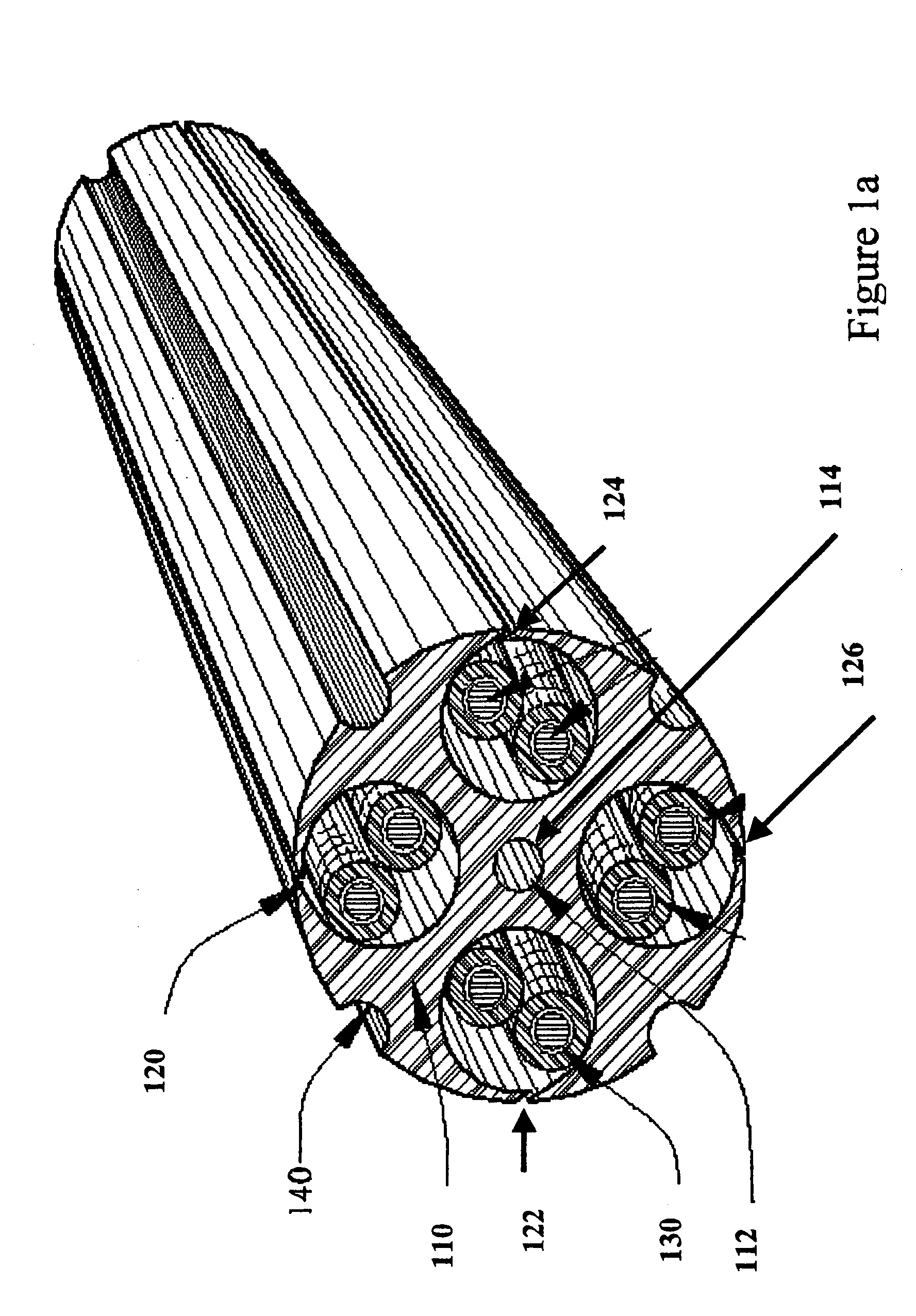
[0089]FIG. 1a is a top-right view of one embodiment of this invention. The shown embodiment has an interior support shown as an anvil-shaped separator (110). The interior support anvil-shaped separator, shown in more detail in FIGS. 3 and 4, runs along the longitudinal length on the cable. The interior support anvil-shaped separator, hereinafter, in the detailed description, referred to as the “anvil-shaped separator”, has a central region (112) extending along the longitudinal length of the cable. The center region includes a cavity that runs the length of the separator in which a strength member (114) may be inserted. Channels 120, 122, 124, and 126 extend along the length of the anvil-shaped separator and provide compartments for conductors (130).

[0090]A strength member may be added to the cable. The strength member (114) in the shown embo...


PUM

PropertyMeasurementUnit
frequenciesaaaaaaaaaa
voltageaaaaaaaaaa

Abstract

A high performance communications cable that includes one or more interior support-seperators with clearance channels that include rifled slots along the length of the channels such that the interior support-separator include anvil shaped sections that are trimmed to reduce extensions of the anvil shaped sections, resulting in enlarged channel openings, wherein the corresponding radial and axial axis is skewed and elongated offsetting any conductor pair from another conductor pair within the clearance channels of the communications cable.

Description

CLAIM TO PRIORITY[0001]This is a continuation of application Ser. No. 10 / 476,085, filed on Oct. 28, 2003, now U.S. Pat. No. 7,0998,405 entitled “High Performance Support-Separator for Communications Cables” to Charles Glew (inventor). Applicants hereby claim priority under all rights to which they are entitled under 35 U.S.C. Section 120 based upon U.S. Pat. No. 6,639,152 filed Aug. 25, 2001 and granted Oct. 28, 2003 and Patent Cooperation Treaty (PCT) patent application (USPTO receiving office) PCT / US02 / 13831 filed at the United States Patent and Trademark Office on May 1, 2002.FIELD OF INVENTION[0002]This invention relates to high performance multi-media communications cables utilizing paired or unpaired electrical conductors or optical fibers. More particularly, it relates to cables having a central core defining singular or plural individual pair channels. The communications cables have interior core support-separators that define a clearance through which conductors or optical ...

Claims


Application Information

Patent Timeline
Patent Type & Authority Patents(United States)
IPC IPC(8): H01B7/00
CPCH01B11/04
Inventor GLEW, CHARLES
Owner CABLE COMPONENTS GROUP
Why Eureka
Try Eureka