Apparatus and method for detecting the loss of a current transformer connection coupling a current differential relay to an element of a power system

a technology of current differential relay and current transformer, which is applied in the direction of electric digital data processing, measurement devices, instruments, etc., can solve the problems of faulted protected elements being isolated from the remainder of the power system, problems such as the operation and the inability of current differential relays to correctly “perceive” short circuits

Active Publication Date: 2007-03-27
SCHWEITZER ENGINEERING LABORATORIES
View PDF13 Cites 42 Cited by
  • Summary
  • Abstract
  • Description
  • Claims
  • Application Information

AI Technical Summary

Benefits of technology

[0016]According to an aspect of the invention, disclosed is a protective relay configured to prevent generation of a trip signal, via operation of the protective relay, when a current transformer connection is lost. The current transformer connection is provided by one of a plurality of current transformers coupling the protective relay to the power system element and providing a corresponding plurality of secondary current waveforms of the three-phase power system to the protective relay. In an embodiment, the protective relay may be a current differential relay. The protective relay includes a signal logic circuit configured to provide a first binary signal in response to receipt of a plurality of like-phase digitized current sample streams derived from the plurality of secondary current waveforms. In an embodiment, a first value of the first binary signal indicates an occurrence of a short circuit in the power system element. The protective relay also includes a lost current transformer (CT) detected logic circuit configured to provide a second binary signal in response to at least one comparison of at least one calculated current value of the plurality of like-phase digitized current sample stream to at least one threshold value. A first value of the second binary signal indicates the current transformer connection loss. A trip logic circuit is coupled to the digital logic circuit and the lost CT detected logic circuit. The trip logic circuit is configured to generate the trip signal when the first binary signal has the first value and the second binary signal has a second value, and to prevent generation of the trip signal when the second binary signal has the first value.
[0017]According to another aspect of the invention, disclosed is an apparatus and method, preferably in a current-based protective relay, for detecting a loss of a current transformer connection provided by one of a corresponding plurality of current transformers coupling the protective relay to a power system element of a three-phase power system and providing a plurality of secondary current waveforms of the three-phase power system to the protective relay. The apparatus includes a first logic circuit configured to provide a first binary signal in response to at least one first comparison of at least one calculated current value of a plurality of like-phase digitized current sample streams to at least one first threshold value of a plurality of threshold values. The plurality of like-phase digitized current sample streams are derived from the plurality of secondary current waveforms. The apparatus also includes a second logic circuit configured to provide a second binary signal in response to at least one second comparison of at least one calculated current value of the plurality of like-phase digitized current sample streams to at least one second threshold value of the plurality of threshold values, and a set reset flip-flop having a set input adapted to receive the first binary signal and a reset input adapted to receive the second binary signal. The set reset flip-flop is configured to provide a third binary signal in response to selective assertion of one of the set input and the reset input. The third binary signal indicates loss of a current transformer connection when the set input is asserted, and indicates no loss of a current transformer connection when the reset input is asserted.

Problems solved by technology

If the operate current exceeds some threshold, or pickup current, the current differential relay issues a tripping signal to one or more power circuit breakers causing it (them) to open and therefore isolate the faulted protected element from the remainder of the power system.
Due to their integral role in current differential relay operation, if a defective current transformer delivers an incorrect or errant secondary current to the current differential relay, problems may arise in current differential relay operation.
Because the incorrect or errant secondary current is not reflective of the actual primary current, it may result in failure of circuit breaker tripping in the event of a short circuit in the protected element, or may result in erroneous tripping when no short circuit exist.
In other words, the current differential relay may incorrectly “perceive” a short circuit or other fault in the protected device when the errant current is actually due to a current transformer problem.
However, if the primary current (e.g. I1) flowing into the protected element exceeds that maximum value, current transformer saturation occurs where the output of the current transformer (e.g. Ī1), or the secondary current, can no longer accurately represent to the current differential relay the actual current flowing into the protective device.
As a result, relay mis-operation may occur when one of the current transformers (connected between the current differential relay and the protected element) saturates and the current differential relay issues a tripping signal to the circuit breaker(s) when no short circuit exists in the protected element.
In such cases, the current differential relay can potentially mis-operate because the missing current creates a false “high” operate current that may potentially exceed the trip threshold and therefore cause an unwanted tripping signal to be issued, despite the absence of a short circuit inside the protected device.
Various prior art algorithms have attempted to address the open CT condition; however all have limitations.
Further, three seconds of stable loading conditions (i.e., total through-load current) are required before the prior art algorithm is enabled, thereby rendering the current differential relay vulnerable to mis-operation during those three seconds in the case of an occurrence of an open CT condition.

Method used


Image

  • Apparatus and method for detecting the loss of a current transformer connection coupling a current differential relay to an element of a power system
  • Apparatus and method for detecting the loss of a current transformer connection coupling a current differential relay to an element of a power system
  • Apparatus and method for detecting the loss of a current transformer connection coupling a current differential relay to an element of a power system

Examples


Embodiment Construction

[0027]Implementation of the system and method for detecting the loss of a current transformer connection disclosed herein prevents a current differential relay from mis-operating when a connection between a CT and the current differential relay is open or short circuited. Further, the embodiments of the system and method disclosed herein are applicable to current differential relays configured to protected a wide range of power system elements such as electrical generators, electrical motors, power transformers, power transmission lines, buses and capacitors, to name a few.

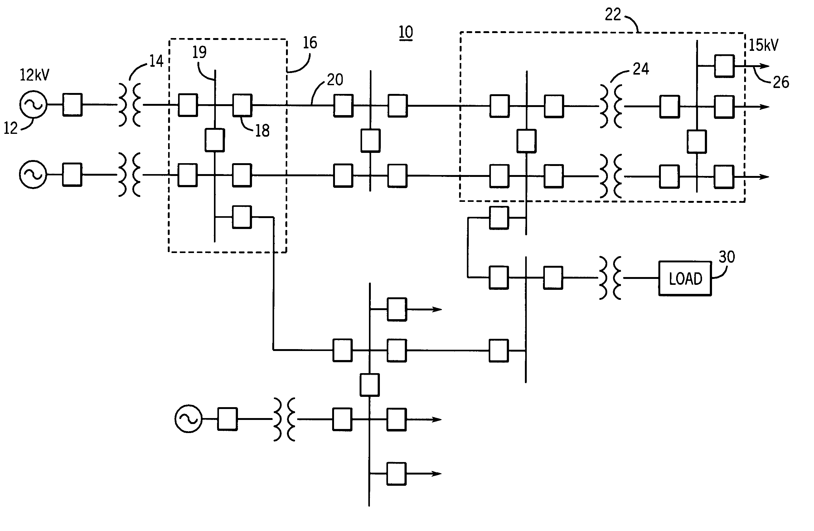
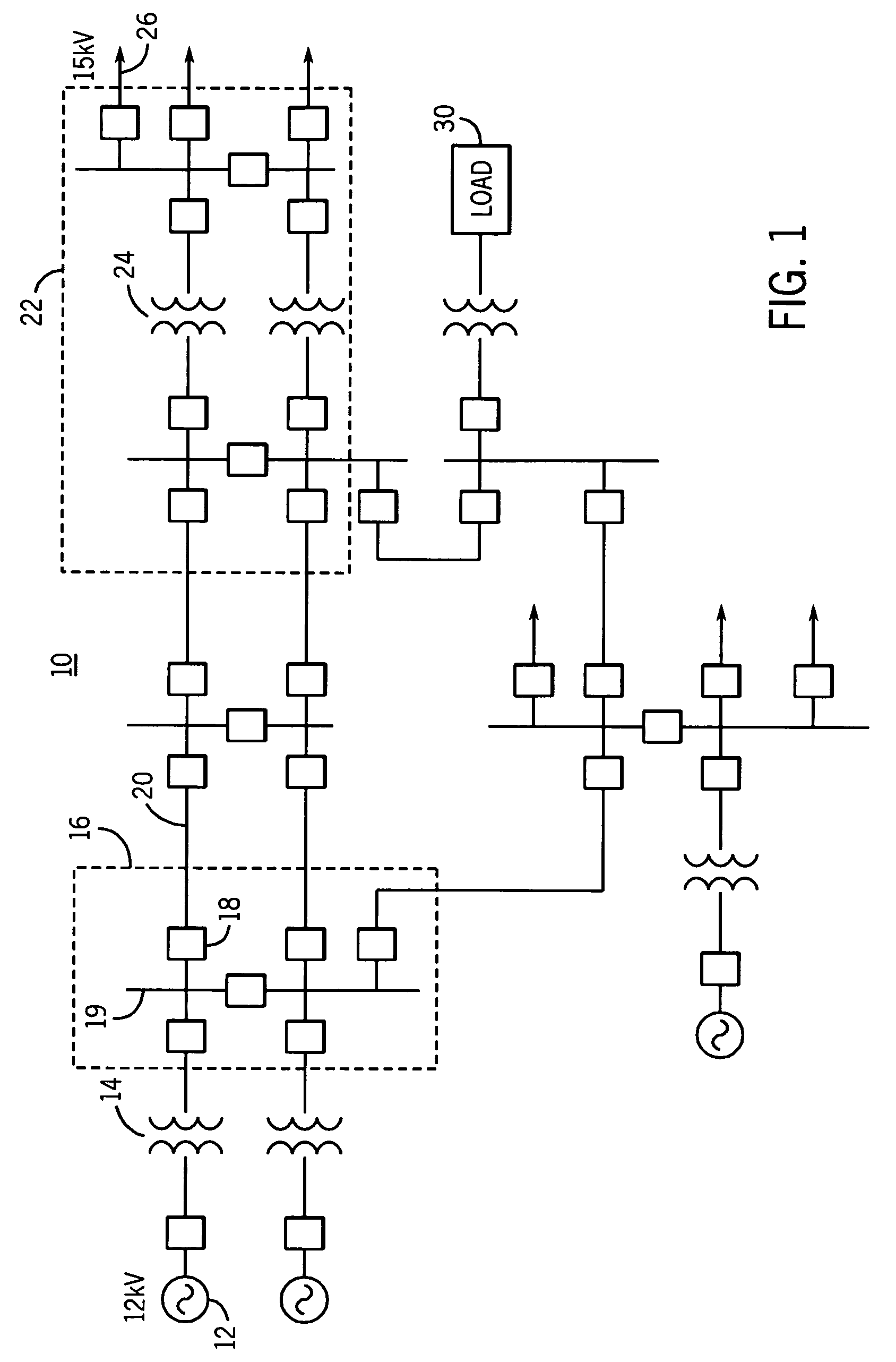
[0028]FIG. 1 is a schematic diagram of a power system 10 that may be utilized in a typical metropolitan area. As illustrated in FIG. 1, the power system 10 includes, among other things, a generator 12 configured to generate three-phase sinusoidal waveforms at, for example, 12 kV, a step-up transformer 14 configured to increase the 12kV sinusoidal waveforms to a higher voltage such as 345 kV, and a first substation...


PUM


Abstract

Disclosed is an apparatus and method for detecting a loss of a current transformer connection coupling a protective relay to a power system element of a three-phase power system and providing a plurality of secondary current waveforms of the three-phase power system to the protective relay. The apparatus includes a first logic circuit and a second logic configured to provide corresponding first and second binary signals in response to respective comparisons of calculated current value(s) of a plurality of like-phase digitized current sample streams to respective threshold values. The apparatus also includes a set reset flip-flop having a set input adapted to receive the first and second binary signals to provide a third binary signal. The third binary signal indicates loss of a current transformer connection when the set input is asserted and indicates no loss of a current transformer connection when the reset input is asserted.

Description

CROSS-REFERENCE TO RELATED APPLICATIONS[0001]NoneBACKGROUND OF THE INVENTION[0002]The present invention generally relates to power system protection, and more specifically, to an apparatus and method for detecting the loss of a current transformer connection coupling a current differential relay to an element of a power system.[0003]Electric utility systems or power systems are designed to generate, transmit and distribute electrical energy to loads. In order to accomplish this, power systems generally include a variety of power system elements such as electrical generators, electrical motors, power transformers, power transmission lines, buses and capacitors, to name a few. As a result, power systems must also include protective devices and procedures to protect the power system elements from abnormal conditions such as electrical short circuits, overloads, frequency excursions, voltage fluctuations, and the like.[0004]In general, protective devices and procedures act to isolate so...

Claims


Application Information

Patent Timeline
Patent Type & Authority Patents(United States)
IPC IPC(8): H02H7/04
CPCH02H5/10H02H3/28
Inventor GUZMAN-CASILLAS, ARMANDOFISCHER, NORMANN
Owner SCHWEITZER ENGINEERING LABORATORIES
Why Eureka
Try Eureka