Frequency plan for GPS receiver

a frequency plan and receiver technology, applied in the field of gps receivers, can solve the problems of reducing the accuracy of time measurement in the receiver design, the sampling bandwidth of the receiver, the number of sampling bits, etc., and achieve the effect of removing interferen

Inactive Publication Date: 2007-03-27
QUALCOMM INC
View PDF20 Cites 12 Cited by
  • Summary
  • Abstract
  • Description
  • Claims
  • Application Information

AI Technical Summary

Benefits of technology

[0009]The present invention provides a GPS receiver having a unique frequency plan, thereby eliminating interference due to internally generated frequencies. In general, the GPS receiver implements a frequency plan based on a frequency of 8.5F where F is 5.115 MHz, and has downconversion circuitry that uses a first synthesizer output signal with a center frequency of 272F to reduce the L1 (308F) or L2 (240F) GPS signal to an intermediate frequency signal. The intermediate frequency signal is then digitized by sampling circuitry wherein the sampling circuitry is driven by a second synthesizer output with a center frequency of 8.5F. The resultant digitized signal contains the GPS information carried in the received GPS signal and has a center frequency of 2F. By selecting 8.5F as the basic reference for all internally generated frequencies, a radio architecture is achieved where all internally generated frequencies are interrelated by nature and no internal signals in the RF-to-baseband conversion can interfere with the received GPS signal within its information bandwidth.

Problems solved by technology

There are several factors that reduce the accuracy of the time measurement in the receiver design, including the sampling bandwidth of the receiver, the number of sampling bits, errors caused by internally generated noise, and external interference.
Additional system factors that cause reduction of accuracy include errors in the ephemeris data (location of the satellite), errors caused by delays due to the ionosphere and troposphere, and multipath errors caused by reflected signals entering the receiver antenna.

Method used


Image

  • Frequency plan for GPS receiver
  • Frequency plan for GPS receiver
  • Frequency plan for GPS receiver

Examples


Embodiment Construction

[0016]The embodiments set forth below represent the necessary information to enable those skilled in the art to practice the invention and illustrate the best mode of practicing the invention. Upon reading the following description in light of the accompanying drawing figures, those skilled in the art will understand the concepts of the invention and will recognize applications of these concepts not particularly addressed herein. It should be understood that these concepts and applications fall within the scope of the disclosure and the accompanying claims.

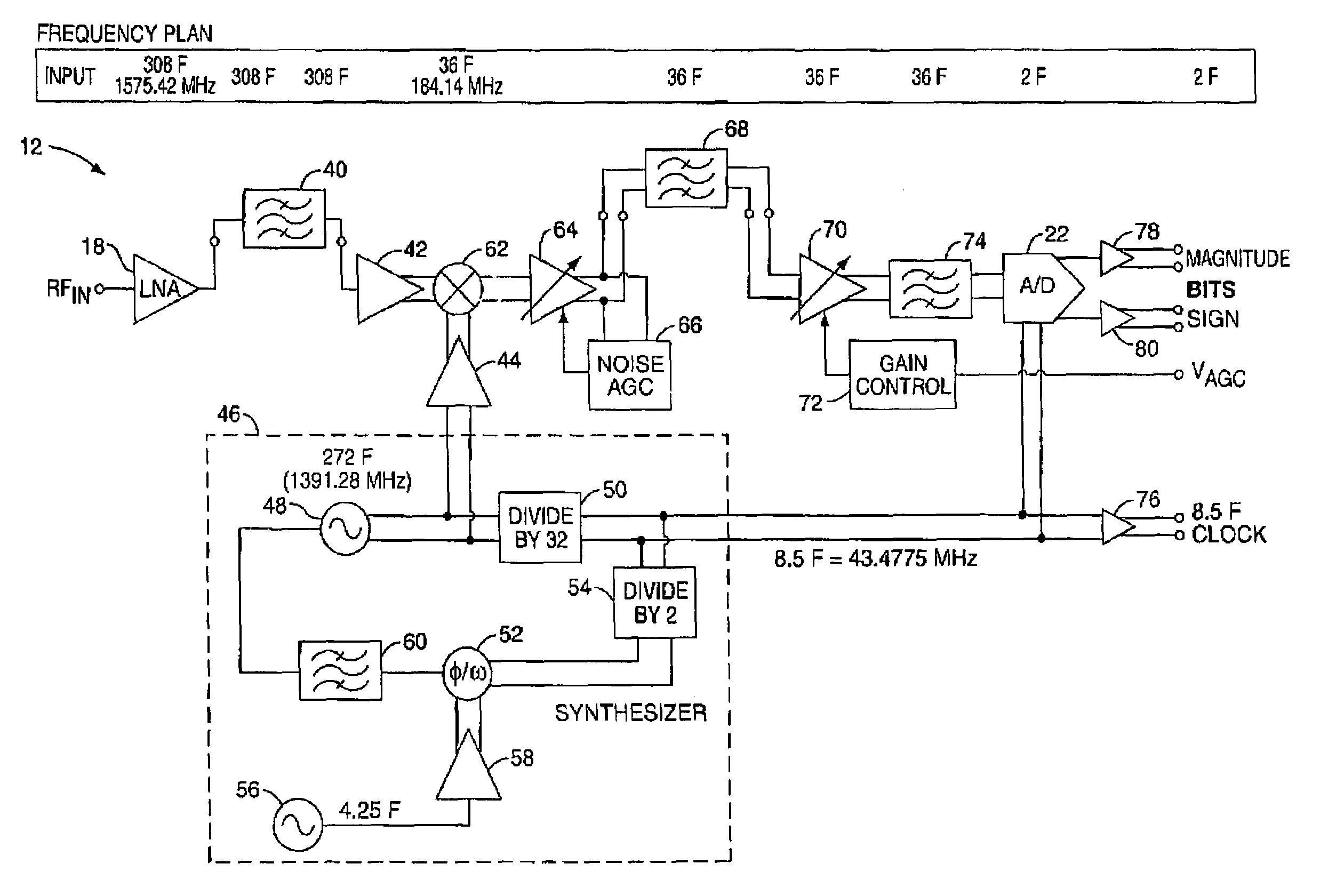
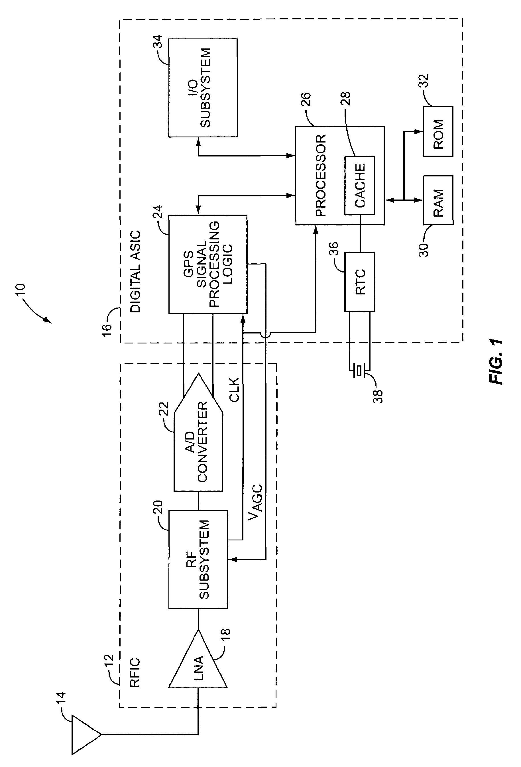
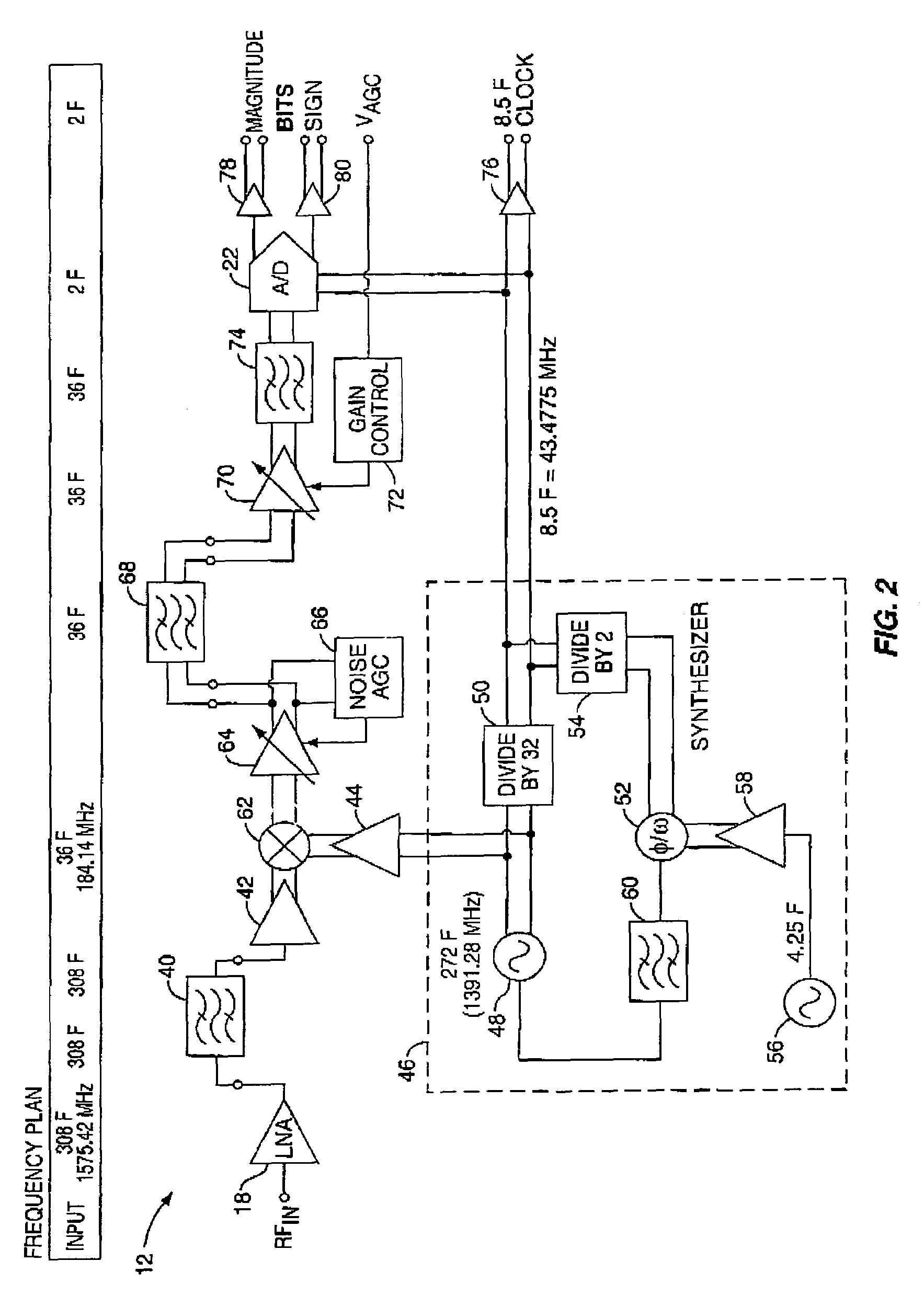
[0017]The present invention is preferably incorporated in a GPS receiver 10. The basic architecture of a GPS receiver 10 is represented in FIG. 1 and may include a radio frequency integrated circuit (RFIC) 12, an antenna 14, and a digital application specific integrated circuit (ASIC) 16. The RFIC 12 receives information previously modulated on a radio frequency carrier from one or more satellite vehicles through antenna 14. A low...


PUM


Abstract

The present invention provides a GPS receiver having a unique frequency plan, thereby eliminating interference due to internally generated frequencies. In general, the GPS receiver has downconversion circuitry that uses a first synthesizer output signal with a center frequency of 272F to reduce the L1 (308F) or L2 (240F) GPS signal to an intermediate frequency signal. The intermediate frequency signal is then digitized by sampling circuitry wherein the sampling circuitry is driven by a second synthesizer output with a center frequency of 8.5F. The resultant digitized signal contains the GPS information carried in the received GPS signal and has a center frequency of 2F. By selecting 8.5F as the basic reference for all internally generated frequencies, where F is 5.115 MHz, all internally generated frequencies are interrelated by nature and no internal signals in the RF-to-baseband conversion can interfere with the received GPS signal within its information bandwidth.

Description

CROSS-REFERENCE TO RELATED APPLICATIONS[0001]This U.S. patent application is related to the following concurrently filed U.S. patent applications:[0002]i.) INTEGRATED GPS RECEIVER ARCHITECTURE by Najarian et al.;[0003]ii.) RF SYSTEM FOR REJECTION OF L-BAND JAMMING IN A GPS RECEIVER by Najarian et al.; and[0004]iii.) ALIAS SAMPLING FOR IF-TO-BASEBAND CONVERSION IN A GPS RECEIVER by Najarian et al., wherein these related U.S. patent applications are incorporated herein by reference in their entireties.FIELD OF THE INVENTION[0005]The present invention relates to GPS receivers, and particularly relates to a unique frequency plan for use in GPS receivers.BACKGROUND OF THE INVENTION[0006]The global positioning system (GPS) is based on an earth-orbiting constellation of twenty-four satellite vehicles each broadcasting its precise location and ranging information. From any location on or near the earth, a GPS receiver with an unobstructed view of the sky should be able to track at least fou...

Claims


Application Information

Patent Timeline
Patent Type & Authority Patents(United States)
IPC IPC(8): H03K9/00G01S1/00
CPCG01S19/21G01S19/36G01S19/37G01S19/32
Inventor NAJARIAN, RICHARD
Owner QUALCOMM INC
Why Eureka
Try Eureka