Intake noise suppressor

a technology of intake manifold and noise suppression, which is applied in the direction of intake silencers for fuel, combustion-air/fuel-air treatment, feed systems, etc., can solve the problems of unwanted acoustic and mechanical stresses, large connecting area must be closed and sealed, and high manufacturing cost, so as to reduce the complexity of mounting the intake manifold and increase the static stability, the effect of maximizing the design spa

Active Publication Date: 2007-04-03
MANN HUMMEL GMBH
View PDF5 Cites 25 Cited by
  • Summary
  • Abstract
  • Description
  • Claims
  • Application Information

AI Technical Summary

Benefits of technology

[0007]A further object of the invention is to provide an intake noise suppressor which can be manufactured easily, reliably and economically.
[0022]In one advantageous embodiment, the resonators are arranged opposite one another on the circumferential side of the main flow cross section. In the case of two resonators arranged in this way, they are preferably aligned at an angle of 180° from one another. In the case of more than two resonators, the angle offset is divided evenly. The individual resonators may each contain multiple resonator chambers. This design forms an advantageous symmetrical intake manifold with a centrally located center of gravity and increased static stability.

Problems solved by technology

Due to the charge cycle of the internal combustion engine, there is a pulsation of air which produces vibration in the intake system and results in unwanted acoustic and mechanical stresses.
One disadvantage of this embodiment is that when the housing walls are joined together, a large connecting area must be closed and sealed.
This connecting area is responsible for a high manufacturing cost and interrupts a smooth course of the pipe wall.

Method used


Image

  • Intake noise suppressor
  • Intake noise suppressor
  • Intake noise suppressor

Examples


Embodiment Construction

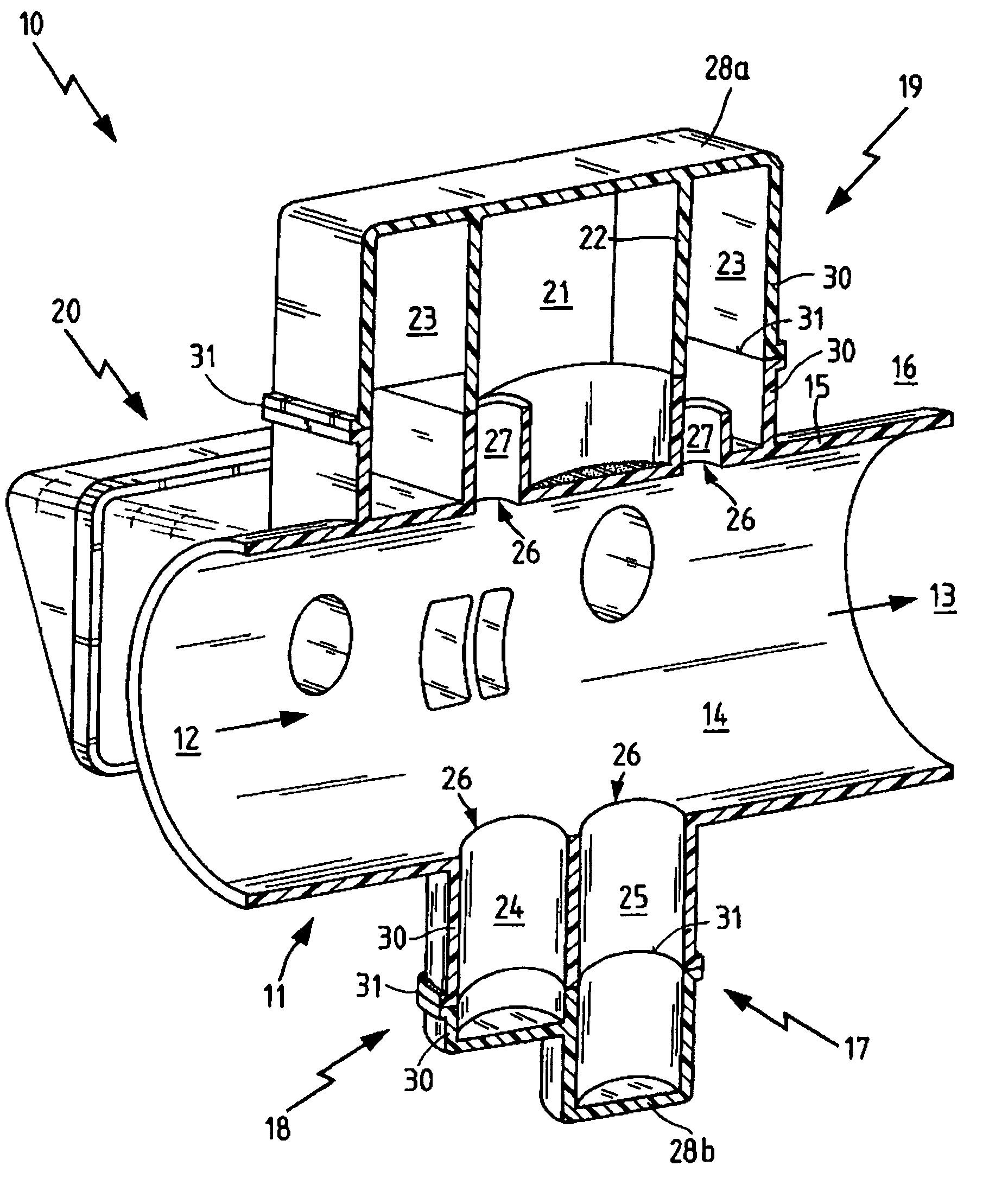
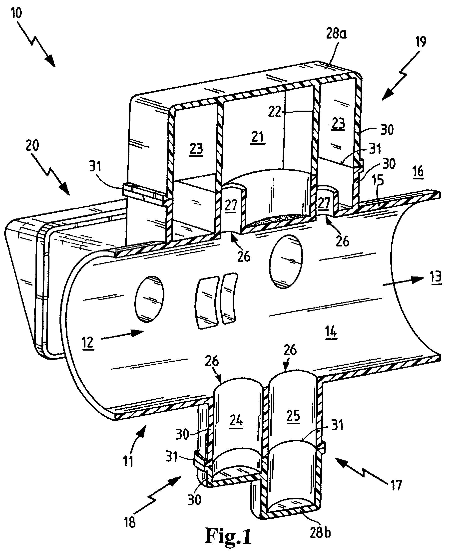
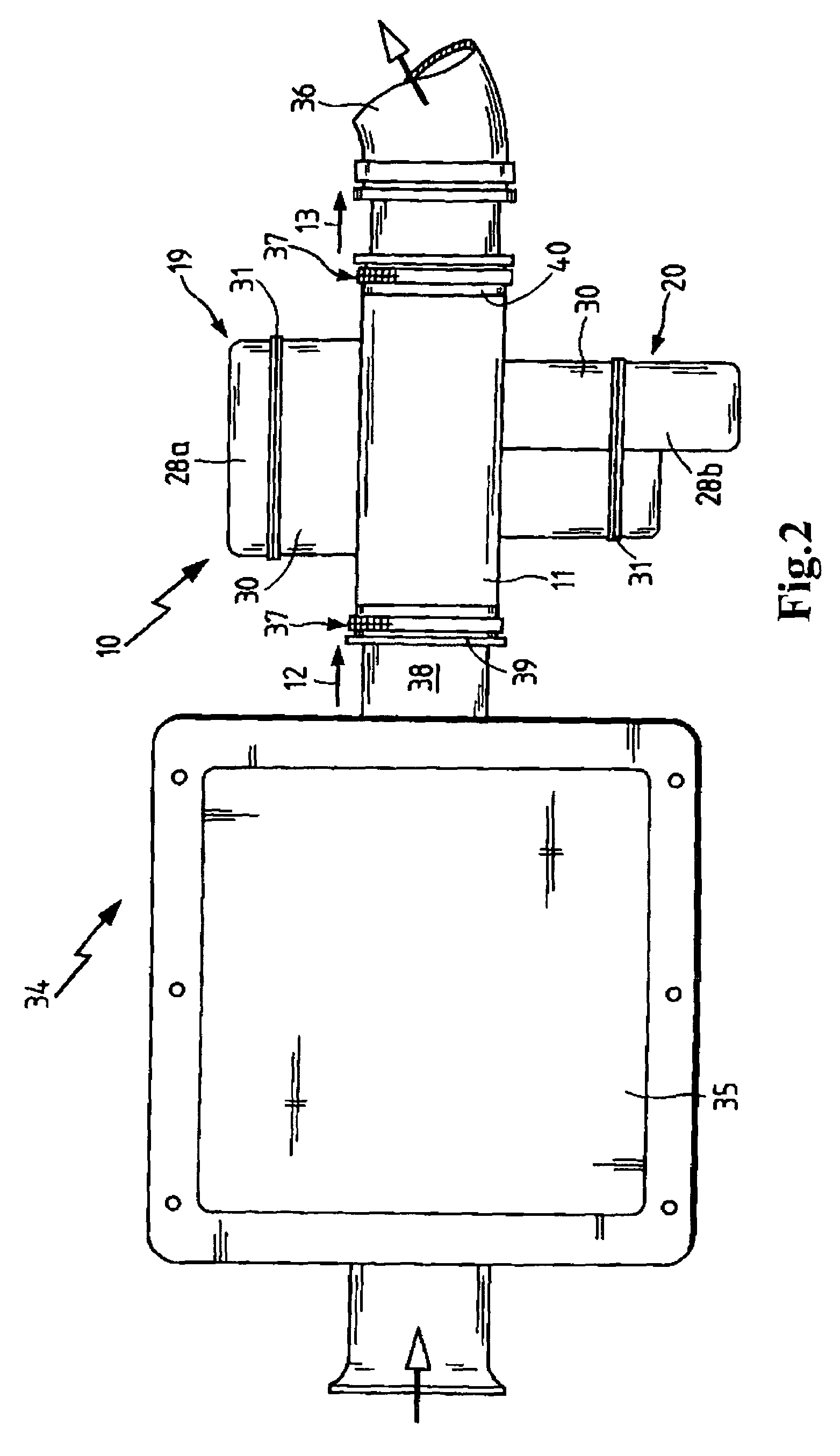
[0027]FIG. 1 shows an intake manifold 10 in a fully sectional perspective view, which has a main flow cross section 14 between an oncoming flow side 12 and an outgoing flow side 13 on a base body 11. The oncoming flow side 12 and the outgoing flow side 13 are connected to components of an air intake tract (See FIG. 2). These connections are preferably designed to be round or oval and may be attached and sealed, for example, by elastomer couplings. The components to be joined may include, for example, throttle valves, clean air pipes, intake manifolds, unfiltered air pipes and / or air filters.

[0028]The main flow cross section 14 is surrounded by walls 15. The walls 15 separate the main flow cross-section 14 from the surrounding ambient environment 16 and from the resonators 17, 18 and 19.

[0029]The resonators include two quarter-wave resonators 17, 18, a double resonator 19 and a multiple resonator 20 which is not shown in cross section. The double resonator 19 forms two Helmholtz reso...


PUM


Abstract

An intake manifold 10 in the air intake tract of an internal combustion engine which has a main flow cross section 14 between an oncoming flow side 12 and an outgoing flow side 13. At least one resonator chamber 23 is arranged on the circumference of the main flow cross section 14 in communication with the main flow cross section 14. The resonator chamber 23 is surrounded by side walls 30 and closed by a cover 28, with the side walls 30 of the resonator chamber 23 and the wall 15 forming the main flow cross section 14 being manufactured together in one piece. A parting plane 31 situated between the cover 28 and the side walls 30 of the resonator chamber 23 is arranged outside of the wall 15 forming the main flow cross section 14.

Description

BACKGROUND OF THE INVENTION[0001]This invention relates to an intake manifold having a main flow channel and at least one resonator chamber disposed thereon in communication with the main flow channel.[0002]Intake manifolds having noise suppressing attributes are used in the air intake tract of internal combustion engines between the unfiltered air inlet and the cylinder head of the internal combustion engine. Due to the charge cycle of the internal combustion engine, there is a pulsation of air which produces vibration in the intake system and results in unwanted acoustic and mechanical stresses.[0003]U.S. Pat. No. 6,009,705 (=EP 859,906) describes a noise suppressor having multiple resonator chambers between a gas inlet and a gas outlet. The tubular resonators and the flow cross section are formed by joining two housing parts. A parting plane runs between the two housing parts along the housing walls of the individual resonators and the main flow cross section.[0004]One disadvanta...

Claims


Application Information

Patent Timeline
Patent Type & Authority Patents(United States)
IPC IPC(8): F02M35/10F02M35/12
CPCF02M35/1266F02M35/1283
Inventor VOGT, SABINEWERNER, JUERGEN
Owner MANN HUMMEL GMBH
Why Eureka
Try Eureka