Compliant heat exchange panel

a heat exchange panel and heat exchange technology, applied in the field of heat exchangers, can solve the problems of increasing the cost of active heat exchange systems, increasing the difficulty of controlling the dimensions of elastic materials, and changing the panel or the medium, so as to reduce buckling, reduce the effect of panel thickness, and increase the area of thermal conta

Inactive Publication Date: 2007-04-03
AVENT INC
View PDF36 Cites 67 Cited by
  • Summary
  • Abstract
  • Description
  • Claims
  • Application Information

AI Technical Summary

Benefits of technology

[0011]It is therefore an object of the present invention to provide a compliant heat exchange panel that is superior to the prior art for conforming and making thermal contact to complex shapes and for providing a more uniform temperature.
[0013]An advantage of a heat exchange panel of the present invention is that a dot matrix attachment pattern is organized for providing a greater area of thermal contact by minimizing the number of dot attachments for a given panel thickness when inflated and maintaining a more constant panel thickness.
[0014]Another advantage of a heat exchange panel of the present invention is that border and fence seals are rippled thereby reducing buckling when the panel is inflated.
[0015]An advantage of an active heat exchange panel of the present invention is that a dot matrix pattern provides a more uniform temperature through better mixing of a fluid flow.
[0016]Another advantage of an active heat exchange panel of the present invention is that border and fence seals have smooth ripples i.e., ripples having no sharp changes in direction as stated above (curvilinear ripples) thereby providing greater compliance and reducing areas of stagnation for a more uniform temperature.

Problems solved by technology

A limitation of a passive heat exchange panel is that the panel or the medium must be changed when the temperature of the medium rises.
An active heat exchange system is more expensive because an external apparatus is required to pump and re-cool the liquid.
Elastic material could be used to alleviate these problems, however, the dimensions of elastic materials are more difficult to control.
However, the hard or, in other words, adrupt corners of the wrinkles decrease the laminar flow of the liquid 120 enabling thermal zones of warmer liquid to form, thereby reducing the performance of the heat exchange panel 200.

Method used


Image

  • Compliant heat exchange panel
  • Compliant heat exchange panel
  • Compliant heat exchange panel

Examples


Embodiment Construction

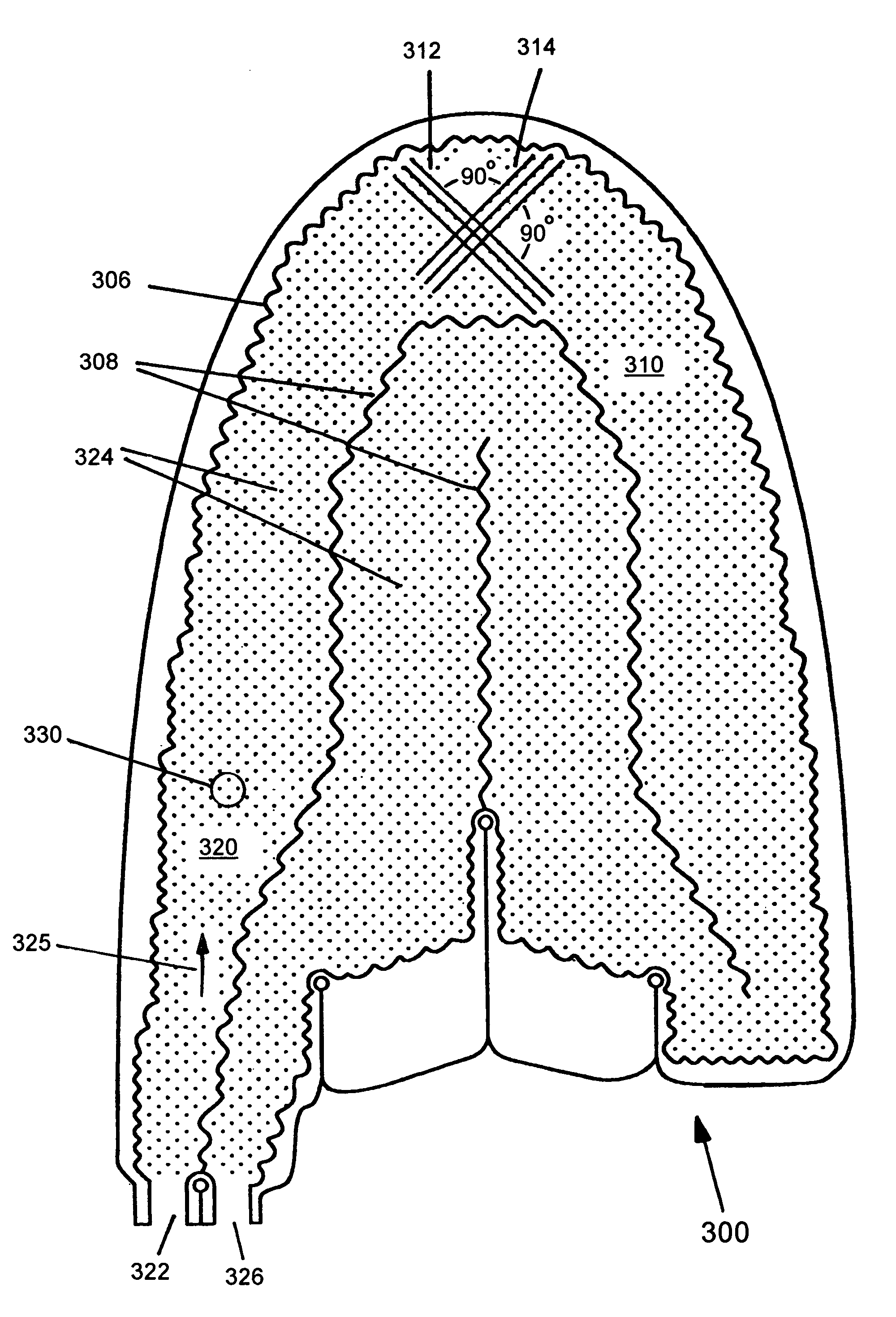
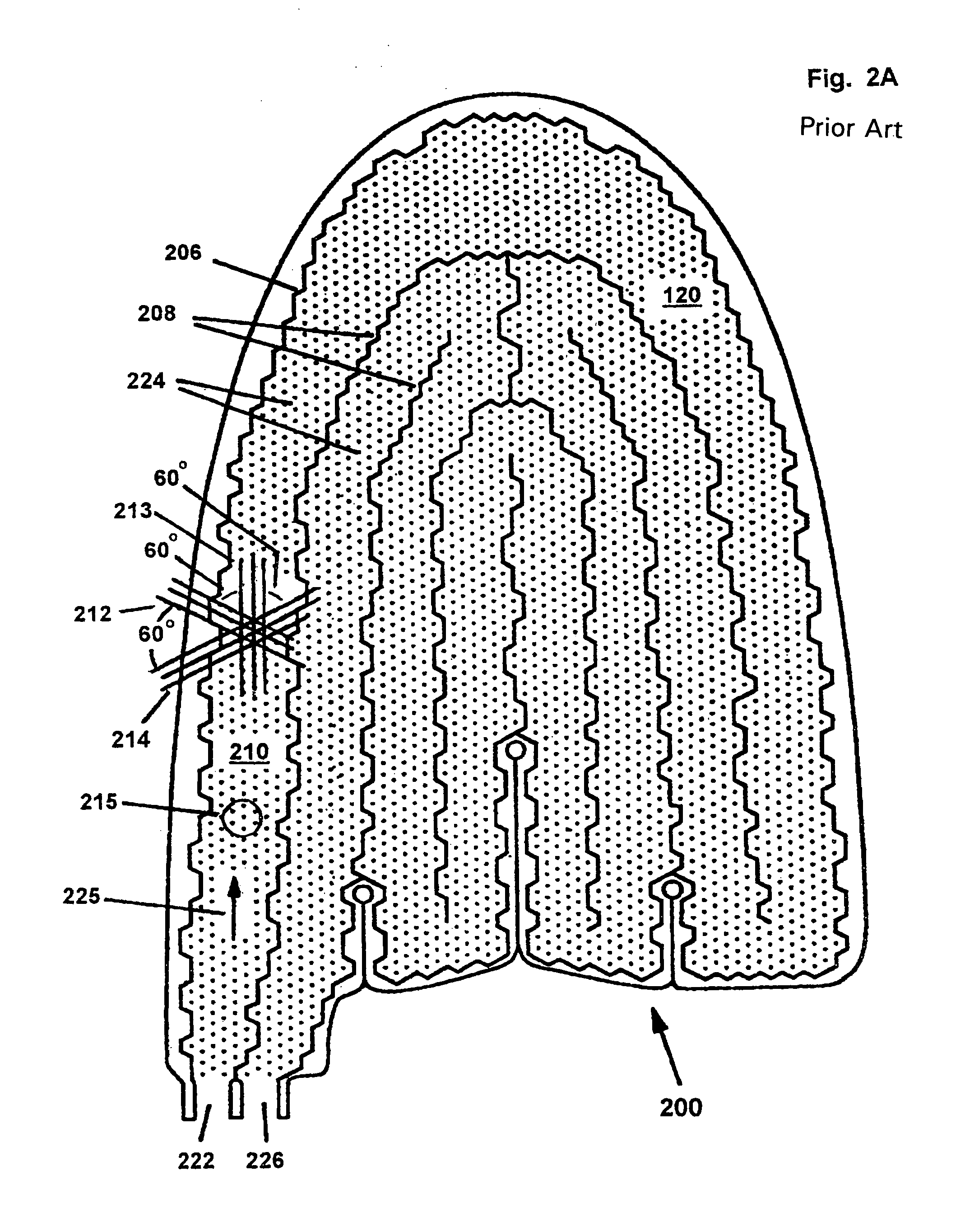
[0024]FIGS. 3A and 3B are a plan and a cross-sectional diagram, respectively, of a heat exchange panel of the present invention and referred to by a reference number 300. The heat exchange panel 300 includes a first layer 302 and a second layer 304. The first layer 302 and the second layer 304, which layers are conformable to complex shapes are sealed together at a common border 306, at fences 308, and at dots of a dot matrix 310. Preferably, the common border 306 is near to the perimeters of the first layer 302 and the second layer 304 but it does not need to be at the exact outside of the first layer 302 or the second layer 304. The dot matrix 310 is organized into first imaginary parallel lines 312 and second imaginary parallel lines 314 for connecting each of the dots to the nearest adjacent dots of the dot matrix 310. The lines 312 and 314 are approximately perpendicular within a range ±20°. In contrast, in the prior art panel 200 (FIGS. 2A–B) the lines 212–14 cross at angles o...


PUM

PropertyMeasurementUnit
angleaaaaaaaaaa
angleaaaaaaaaaa
anglesaaaaaaaaaa

Abstract

A heat exchange panel for use in an active heat exchange system. The heat exchange panel includes first and second layers having seals between the layers at a common border, at fences, and at dots of a dot matrix. The dot matrix is organized into first parallel lines and second parallel lines where the first and second parallel line cross at a 90° angle. The seals at the border and the fences are rippled with smooth ripples.

Description

BACKGROUND OF THE INVENTION[0001]1. Field of the Invention[0002]The invention relates generally to heat exchangers and more particularly to a thin flexible heat exchange panel for transferring heat to or from a complex shape such as a portion of a human body.[0003]2. Description of the Prior Art[0004]Compliant heat exchange panels are used for cooling a portion of a human body for physical therapy, pre-game day conditioning, minor injury care, post orthoscopic surgery recovery, and as a replacement for general air-conditioning. The heat exchange panels operate by transferring heat from the human body to a heat absorbing medium having a lower temperature than the body. The heat exchange panel may be passive where the medium is stationary within the panel or active where the medium, typically a liquid, flows through the panel. A common example of a passive heat exchange panel is an ice pack. A limitation of a passive heat exchange panel is that the panel or the medium must be changed ...

Claims


Application Information

Patent Timeline
Patent Type & Authority Patents(United States)
IPC IPC(8): F28F3/12A61F7/08A61F7/00A61F7/02
CPCA61F7/02Y10T29/49366A61F2007/0274A61F2007/0056
Inventor ELKINS, WILLIAM
Owner AVENT INC
Why Eureka
Try Eureka