High-voltage hybrid circuit-breaker

a hybrid circuit and high-voltage technology, applied in the direction of contact mechanisms, high-tension/heavy-dress switches, air-break switches, etc., can solve the problems of short assembly time, reduced production cost, and reduced production cos

Active Publication Date: 2007-04-03
ALSTOM TECH LTD
View PDF9 Cites 19 Cited by
  • Summary
  • Abstract
  • Description
  • Claims
  • Application Information

AI Technical Summary

Benefits of technology

[0028]By appropriately choosing the angle of inclination of the second segment, it is possible to adjust the speed of separation of the contacts of the vacuum bottle.

Problems solved by technology

This results in a smaller number of parts, a lower cost, and a shorter assembly time.

Method used


Image

  • High-voltage hybrid circuit-breaker
  • High-voltage hybrid circuit-breaker
  • High-voltage hybrid circuit-breaker

Examples


first embodiment

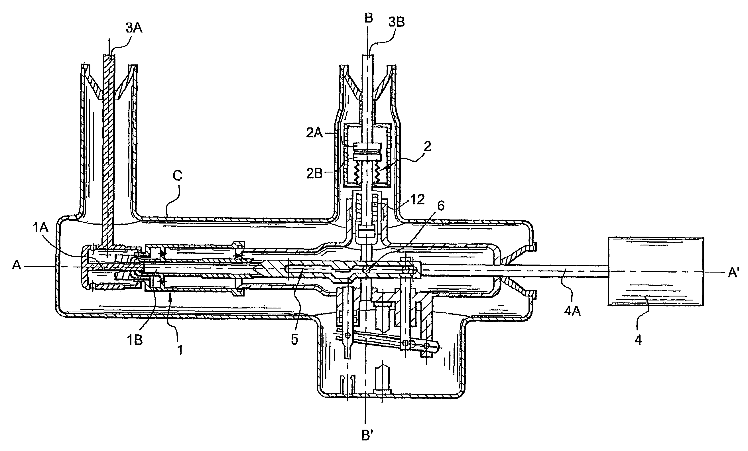
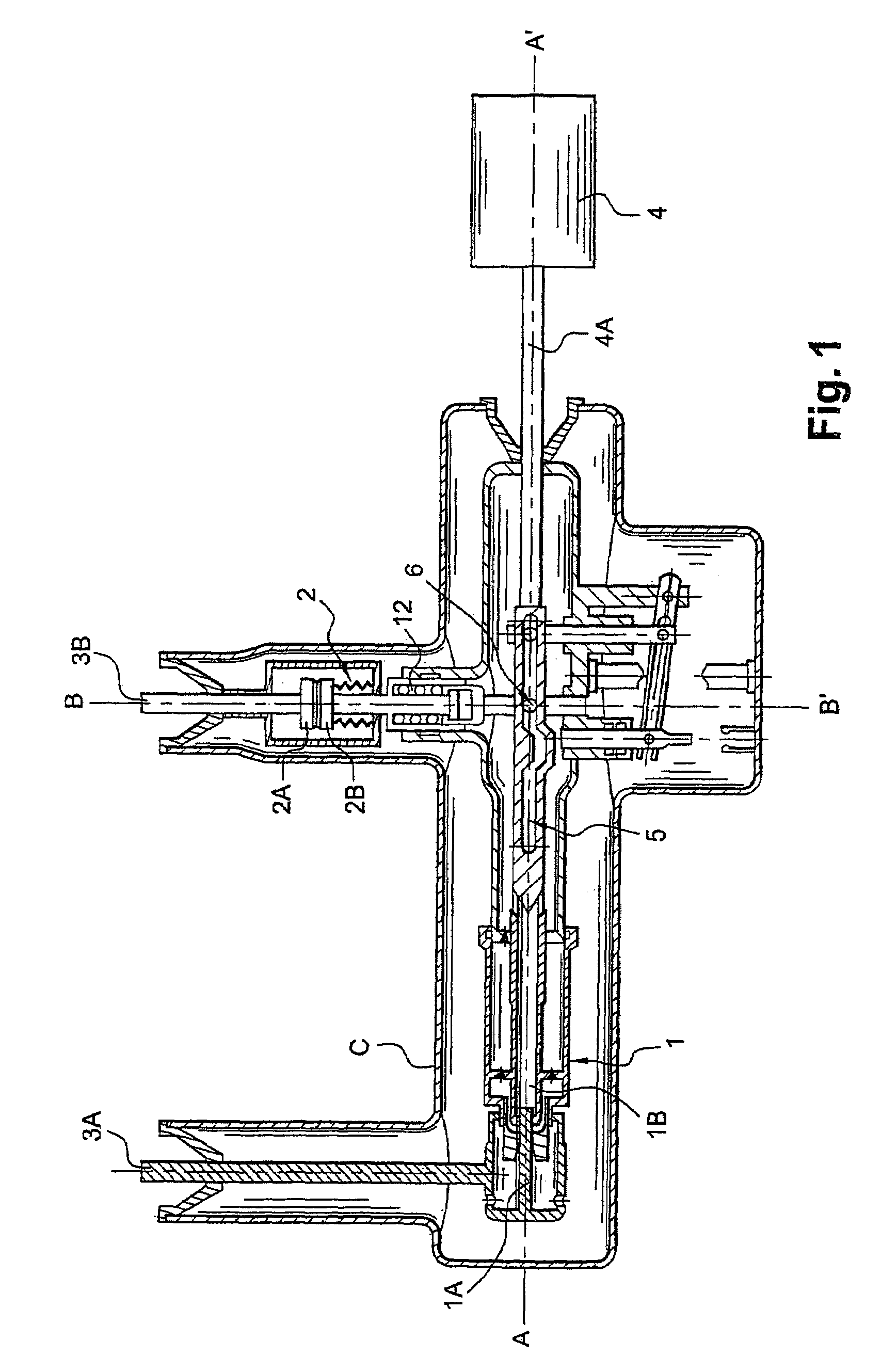
[0048]A first embodiment is described below with reference to FIGS. 1 to 4, which show a metal-clad hybrid circuit-breaker having metal cladding C that is grounded.

[0049]In this example, the slideway is formed by a groove 5 provided in a piece extending the moving contact 1B and connecting said contact to the control link 4A, and the element connected to the moving contact 2B of the vacuum bottle 2 is a lug or peg 6 that is perpendicular to the second axis BB′ and that is engaged in said groove 5.

[0050]In order to achieve the desired synchronization of the moving contacts 1B and 2B, the groove 5 is shaped as follows.

[0051]In order to perform the function of opening the vacuum bottle 2 with a delay of a few ms relative to opening of the interrupting chamber 1, the groove has a first segment 5A parallel to the first axis AA′, disposed closer to the control 4 and extended at its end closer to the moving contact 1B of the interrupting chamber 1 by a second segment 5B that slopes away fr...

second embodiment

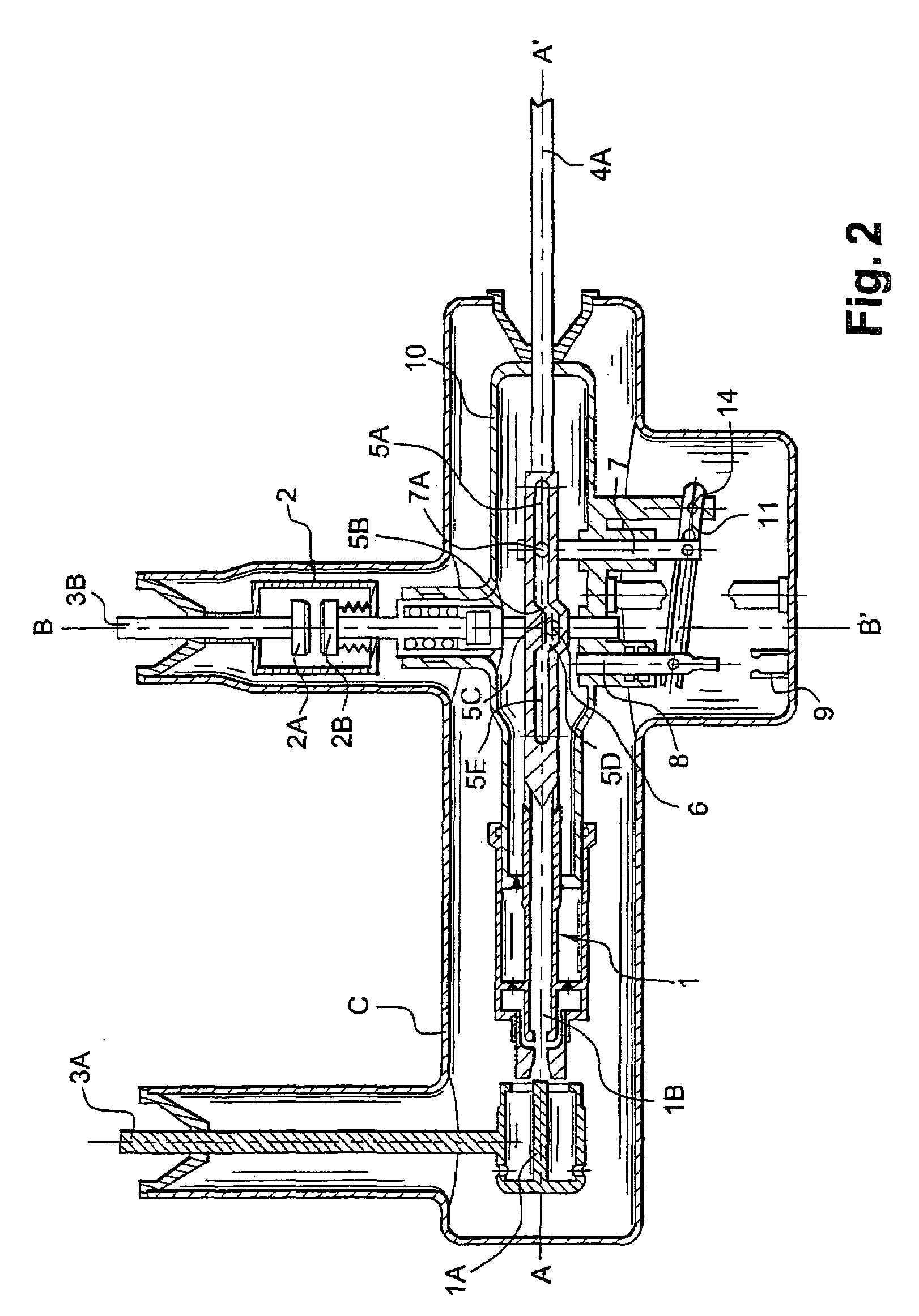
[0064]FIG. 5 shows a second embodiment including a variant embodiment of the automatic grounding arrangement.

[0065]In this example, at its end closer to the control 4, the longitudinal drive arrangement or slideway carries a contact 8′ having a longitudinal axis AA′, and the distance between the contact 8′ and the cladding C which carries a grounded contact 9′ that is preferably of the thimble contact type, is such that, at the end of the stroke over which the control link 4A moves longitudinally, into the position in which the interrupting chamber acts as a disconnector, said contact 8′ comes into electrical contact with the thimble contact 9′, thereby providing grounding.

third embodiment

[0066]FIG. 6 shows the invention, in the closed position, and including another variant of the drive means.

[0067]In this example, the slideway is formed by a link 5′ extending the moving contact 1B and connecting said moving contact to the control link 4A, and the element connected to the moving contact 2B of the vacuum bottle 2 is a lug or peg 6′ that is perpendicular to the second axis BB′ and that rolls against the slideway link 5′. The link 5′ comprises segments 5′A to 5′E analogous to the above-described segments in the first embodiment which has a groove 5 and which operates identically.

[0068]The peg 6′ carries a rolling bearing and is inserted between the bottom face or generator line of the link 5′ and a piece 7′ connected to the moving contact 2B of the vacuum bottle 2. The piece 7′ is a clevis-shaped piece and is advantageously held in sliding contact by a support 8′ carried by the casing 10.

[0069]FIGS. 7 and 8 are fragmentary views showing such a circuit-breaker during an...


PUM


Abstract

The invention relates to a hybrid circuit-breaker which, for each pole, comprises a dielectric-gas interrupting chamber (1) which contains a first contact (1A) and a moving second contact (1B) that are disposed longitudinally to a first axis (AA′) and in which the first contact (1A) is connected to a first terminal (3A) of the network, said interrupting chamber (1) being connected in series with a vacuum bottle (2) which contains a fixed contact (2A) and a moving contact (2B) that are disposed longitudinally to a second axis (BB′) and in which the fixed contact (2A) is connected to a second terminal (3B) of the network, actuating means acting via a single control (4) to move said moving contacts between respective open positions and respective closed positions. According to the invention, said actuating means comprise a re-closure arrangement for re-closing the moving contact (2B) of the vacuum bottle, which re-closure arrangement enables said single control (4) to perform such re-closure before the moving contact (1B) of said interrupting chamber reaches its open position.

Description

CROSS-REFERENCE TO RELATED APPLICATION[0001]This application claims priority to French Application No. 04 50588, filed on Mar. 25, 2004, entitled: “A High-Voltage Hybrid Circuit-Breaker” by Michel PERRET and was not published in English.BACKGROUND OF THE INVENTION[0002](1) Field of the Invention[0003]The present invention relates to high-voltage circuit devices. More specifically, the present invention relates to a high-voltage hybrid circuit-breaker.[0004](2) Description of Related Art[0005]The present invention relates to a high-voltage hybrid circuit-breaker.[0006]Such a hybrid circuit-breaker comprises one interrupting chamber for each pole, which interrupting chamber uses a dielectric gas, e.g. sulfur hexafluoride (SF6) under pressure, and has its fixed contact connected to a first terminal of the network and connected in series with a switch that withstands the dU / dt of the re-establishment voltage transient, and that has its fixed contact connected to a second terminal of the...

Claims


Application Information

Patent Timeline
Patent Type & Authority Patents(United States)
IPC IPC(8): H01H9/40H01H33/14H01H33/666
CPCH01H33/143H01H33/6661
Inventor PERRET, MICHEL
Owner ALSTOM TECH LTD
Why Eureka
Try Eureka