Refrigeration unit

a refrigerating unit and refrigeration technology, applied in the field of refrigerating units, can solve the problems of high investment, low efficiency, and disadvantages of absorption refrigerating units, and achieve the effects of low efficiency, high investment, and low cos

Inactive Publication Date: 2007-04-10
SCHNEIDER & PARTNER INGGES +1
View PDF11 Cites 5 Cited by
  • Summary
  • Abstract
  • Description
  • Claims
  • Application Information

AI Technical Summary

Benefits of technology

[0004]It is the objective of the invention to provide a refrigerating unit of the type stated initially which can be operated in a reliable, effective, and operation-friendly manner by means of a thermal solar system, in particular in the lower to average refrigerating capacity range.
[0007]The refrigerating unit characterized by a closed fuel circuit can be formed as a hermetically closed, compact unit which is distinguished by an advantageous independence of site. It is operated merely by means of thermal energy and thus advantageously needs no electrical power supply. Since no components working mechanically within the refrigerating unit, such as, for example, pumps, are required to operate the refrigerating unit, the unit is maintenance-friendly, relatively favorable from the standpoint of cost, and can be operated, at least nearly, without noise. Furthermore, it is possible to develop the refrigerating unit so that the mounting of several refrigerating units in parallel can be realized in a relatively simple manner.
[0008]Preferably, the thermal solar system can be actively connected to an expeller formed as a gas bubble pump for the desorption and vaporization of a fuel contained in a solution. A gas bubble pump is particularly suitable for desorbing and vaporizing, in a manner which is effective and favorable for operation, a fuel contained in a solution such as, for example, ammonia (NH3) in an ammonia-rich solution. Furthermore, a gas bubble pump permits an efficient heat transfer accomplished by means of a thermal energy source, which is a prerequisite for reliable and effective desorption and vaporization of the fuel (ammonia).
[0009]According to a preferred form of embodiment, the expeller has at least one rising tube which on the inlet side is provided with a ribbing promoting the vaporization of the fuel contained in the rising tube. The rising tube of the expeller formed as a gas bubble pump contains a solution which is high in fuel and which, due to the vaporization of the fuel in the rising tube, experiences an increase in volume so that it assumes an operating volume which is a multiple of the original volume value, i.e. of the still not vaporized fuel. Due to this increase in volume, the level of the vaporous fuel, or of the fuel mixture in the rising tube, rises to a corresponding operational conveyance height. If this operational conveyance height exceeds the length of the rising tube due to a corresponding increase in volume of the fuel mixture or a vaporization of the fuel, the conveyance of the vaporous fuel, or a remaining solution which is low in fuel, to additional functional units of the refrigerating unit is started, said functional units being actively connected to one another in the form of a closed fuel circuit so that the refrigerating unit is activated at this moment in its operation. In so doing, an effective heat transfer from a thermal energy source (solar system) into the expeller or into the rising tube serves for a reliable and rapid activation of the refrigerating unit. This is guaranteed by means of a suitable ribbing of the rising tube whereby an enlargement of the heat transfer surface to improve the heat transfer into the rising tube is obtained. Instead of ribbing, deflecting plates can also be provided.
[0010]Advantageously, the expeller has a plurality of parallel rising tubes spaced at a distance from one another for the conveyance of a solution which is high in fuel, where a parallel recycling line for the conveyance of the solution which is low in fuel is disposed between at least two rising tubes. This makes possible an expeller formation which is compact and has the form of a bundle of tubes, where advantageously the rising tubes disposed externally can be energized with thermal energy, in a manner favorable to efficiency and operation, by means of a thermal energy source (solar system) while the interposed, parallel recycling line, through which a heated solution which is low in fuel is conveyed, makes possible an additional heating of the outer rising tubes, or counteracts a cooling of the same. The amount of heat radiating, and thus not actively utilized, is reduced in an effective manner due to a compact arrangement of the outer rising tubes as a bundle of tubes and a centrally disposed recycling line.
[0012]Advantageously, the fuel vapor supply line leads essentially coaxially through the recycling line. An expeller of this type is formed particularly compactly and is distinguished by a particularly effective and reliable desorption and vaporization of a fuel in a solution which is high in fuel, said solution being contained in the respective rising tube, since an undesirable radiation of heat from the expeller into the environment can be reduced to a significant extent due to its compact arrangement as a bundle of tubes.

Problems solved by technology

For solar operation, these absorption refrigerating units disadvantageously require a high outlay with regard to control technology and investment, in particular with regard to a continuous reheating or heat storage.
In view of this, absorption refrigerating units are limited to a relatively narrow temperature and flow range.
Also the known, photovoltaically operated compression refrigerating units are characterized by a high outlay with regard to investment and have relatively low efficiency.
These known refrigerating units are not suited to problem-free and economical operation with thermal solar systems, in particular in the average capacity range.

Method used


Image

  • Refrigeration unit
  • Refrigeration unit
  • Refrigeration unit

Examples


Embodiment Construction

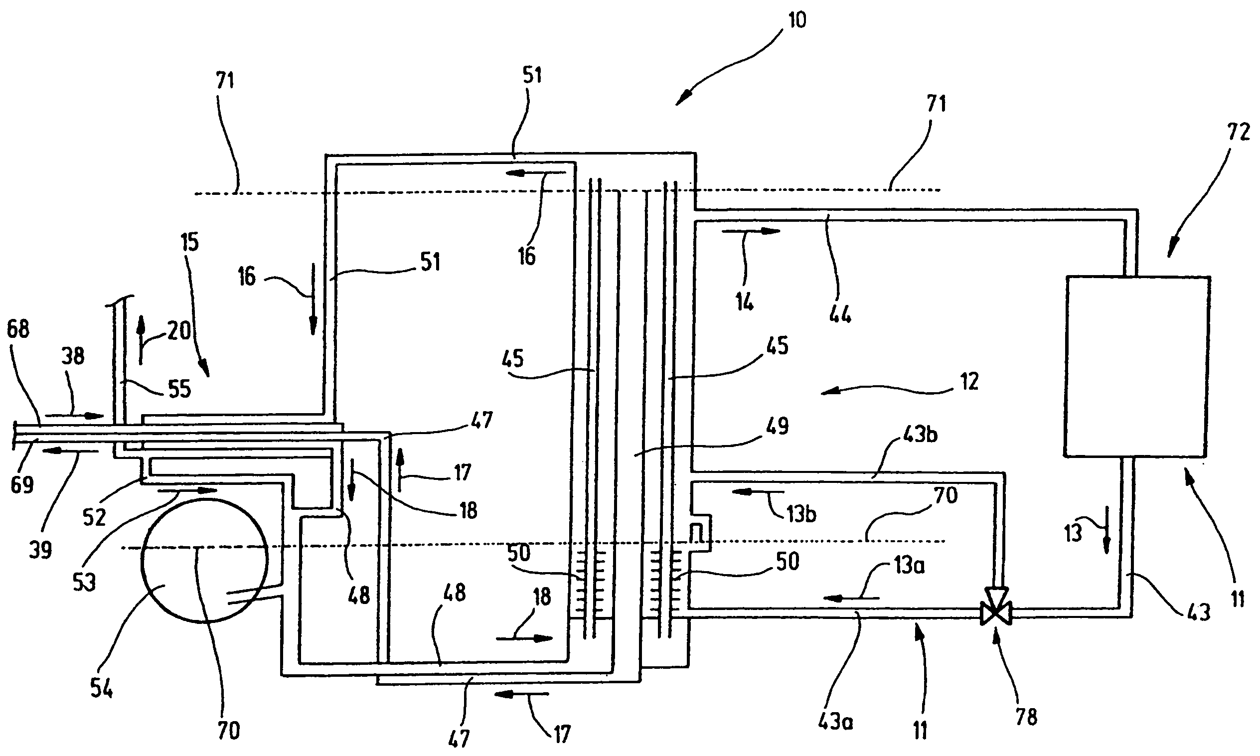
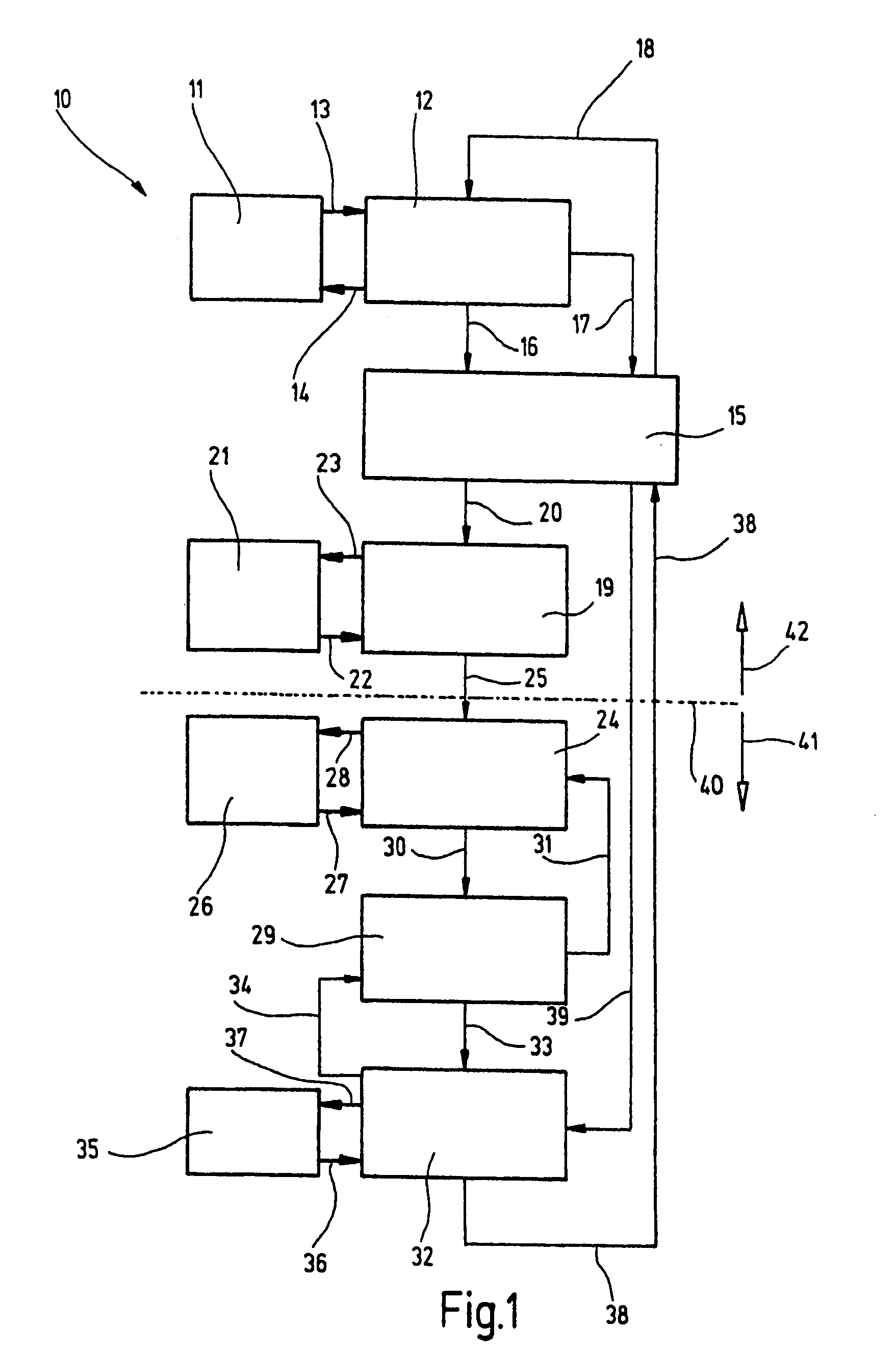
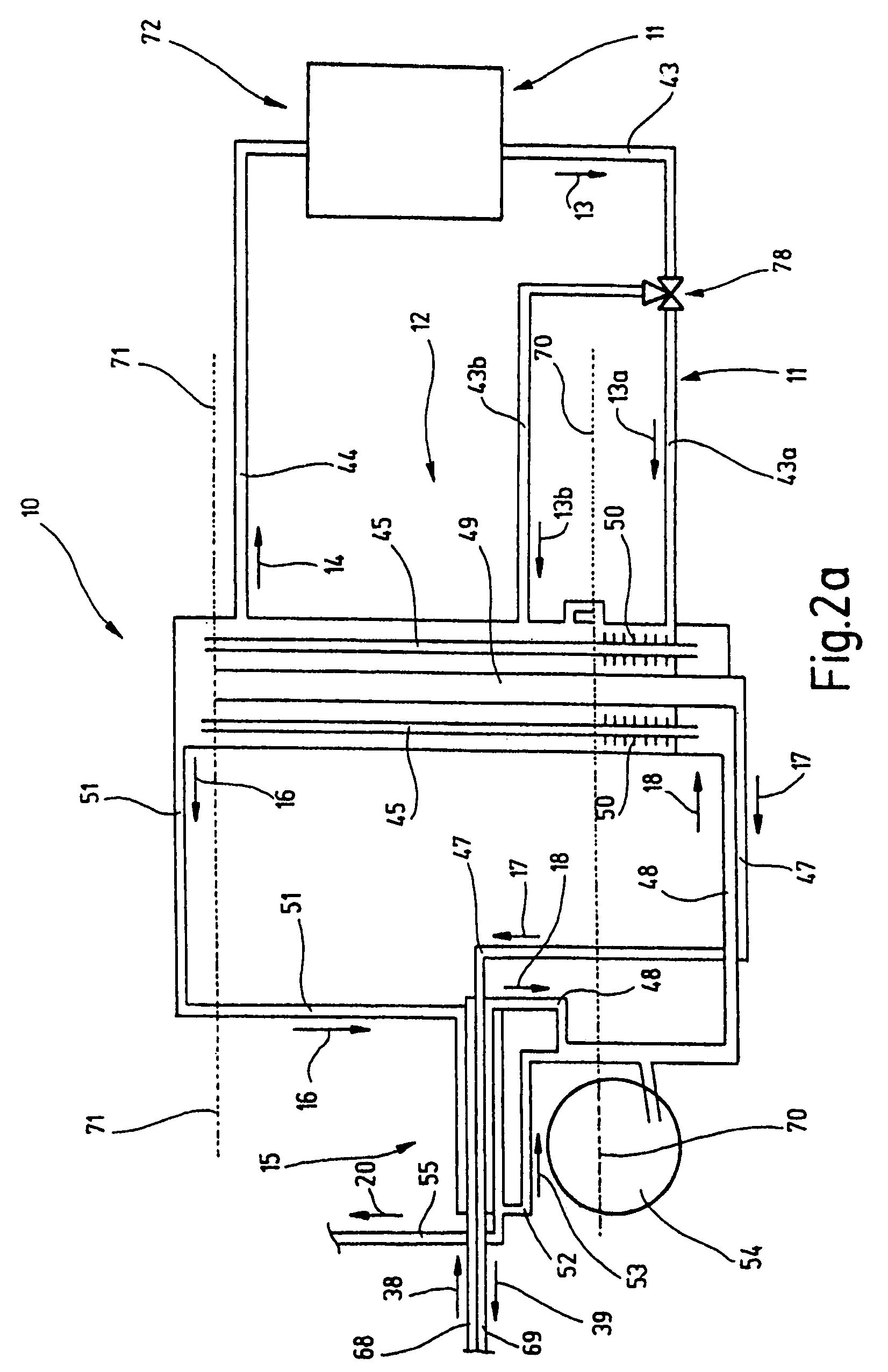
[0023]FIG. 1 shows a block diagram of a refrigerating unit 10. Furthermore, FIGS. 2a and 2b, which complement one another as partial figures, show the refrigerating unit 10 according to FIG. 1 in schematic representation. The refrigerating unit 10 has an expeller 12 which is actively connected to a thermal solar system 11 by means of heat transfer medium lines represented as arrows 13 and 14 (FIG. 2a: 43, 43a, 43b, 44). A fuel vapor supply line represented as an arrow 16 (FIG. 2a: 51) and a supply line, represented as an arrow 17 (FIG. 2a: 47) and serving to convey a solution which is low in fuel, leads from the expeller 12 to a triple heat exchanger 15, from which a supply line, represented as an arrow 18 (FIG. 2a: 48) and serving to convey a solution which is high in fuel, leads to the expeller 12. The triple heat exchanger 15 is actively connected to a condenser 19 by means of a supply line, represented as an arrow 20 (FIGS. 2a / 2b: 55), for fuel vapor and, if needed or desired, w...


PUM


Abstract

The refrigerating unit can be operated by means of a thermal solar system as energy source. Therein it is provided that the refrigerating unit is formed as a diffusion-absorption refrigerating unit. The refrigerating unit has an expeller, a triple heat exchanger, a condenser, an evaporator, a gas heat exchanger, an absorber, and a fuel reservoir which are actively connected to form a closed fuel circuit with one another.

Description

RELATED APPLICATIONS[0001]The present application is the U.S. National Phase of PCT Application PCT / EP01 / 06412, filed Jun. 6, 2001, which claims priority to German Patent Application No. 10028543.0, filed Jun. 8, 2000.BACKGROUND[0002]The invention relates to a refrigerating unit, which can be operated by means of a thermal solar system as energy source, according to the preamble of claim 1.[0003]Refrigerating units of the type addressed here, such as, for example, absorption refrigerating units or compression refrigerating units, are known. For solar operation, these absorption refrigerating units disadvantageously require a high outlay with regard to control technology and investment, in particular with regard to a continuous reheating or heat storage. In view of this, absorption refrigerating units are limited to a relatively narrow temperature and flow range. Also the known, photovoltaically operated compression refrigerating units are characterized by a high outlay with regard t...

Claims


Application Information

Patent Timeline
Patent Type & Authority Patents(United States)
IPC IPC(8): F25B15/00F25B15/10F25B27/00
CPCF25B15/10F25B27/007Y02B30/62Y02A30/27
Inventor BARTH, ULRICHSCHNEIDER, DIETRICHNEGRO, EMANUELEVEELKEN, HELNER
Owner SCHNEIDER & PARTNER INGGES
Why Eureka
Try Eureka