
Pressure accumulation fuel injection controller

a fuel injection controller and pressure accumulation technology, applied in the direction of electric control, liquid fuel feeders, machines/engines, etc., can solve the problems of deteriorating combustion efficiency, difficult burning, and insufficient atomization of fuel, so as to improve the injection amount accuracy of the fuel injection valve, stable combustion state, and stable operation performance

Active Publication Date: 2007-04-10
DENSO CORP
View PDF9 Cites 5 Cited by
  • Summary
  • Abstract
  • Description
  • Claims
  • Application Information

AI Technical Summary

Benefits of technology

[0010]It is an object of the present invention to provide a pressure accumulation fuel injection controller that improves injection amount accuracy of a fuel injection valve and achieves a stable combustion state and stable operation performance by smoothing an injection pressure during an injection period.
[0011]According to an aspect of the present invention, a pressure accumulation fuel injection controller has a pressure accumulation vessel for accumulating high-pressure fuel, a fuel injection valve for injecting the high-pressure fuel accumulated in the pressure accumulation vessel into respective cylinders of an engine, and a fuel supply pump for pressurizing suctioned fuel and for pressure-feeding the fuel to the pressure accumulation vessel. The fuel injection controller has a pressure pattern estimation device, a surplus pressure range calculation device and a pressure reduction valve. The pressure pattern estimation device is configured with an injection period based on a required injection amount and a target common rail pressure and estimates a pressure transition of the fuel in the pressure accumulation vessel during the injection period. The surplus pressure range calculation device is configured with the target common rail pressure based on pressure pattern data provided by the pressure pattern estimation device and calculates a surplus pressure range in which the pressure pattern data during the injection period exceeds the target common rail pressure. The pressure reduction valve discharges the common rail pressure to a lower-pressure side to eliminate the surplus pressure range calculated by the surplus pressure range calculation device. Thus, the injection pressure during the fuel injection period of the fuel injection valve is smoothed. As a result, a stable combustion state can be obtained and operation performance can be stabilized.

Problems solved by technology

However, the fuel is not atomized well when the eruption pressure is low.
In this case, the fuel is difficult to burn and the smoke can be generated easily, deteriorating the combustion efficiency.
Accordingly, the combustion is not stabilized, so engine performance varies and is destabilized.
However, the control of the fuel supply pump is difficult because the fuel supply pump works with the engine.
However, this fuel injection device does not invariably control the pressure reduction valve.
Therefore, problems of instable combustion of the engine and variation or instability of the engine performance still remain.

Method used


Image

  • Pressure accumulation fuel injection controller
  • Pressure accumulation fuel injection controller
  • Pressure accumulation fuel injection controller

Examples


Embodiment Construction

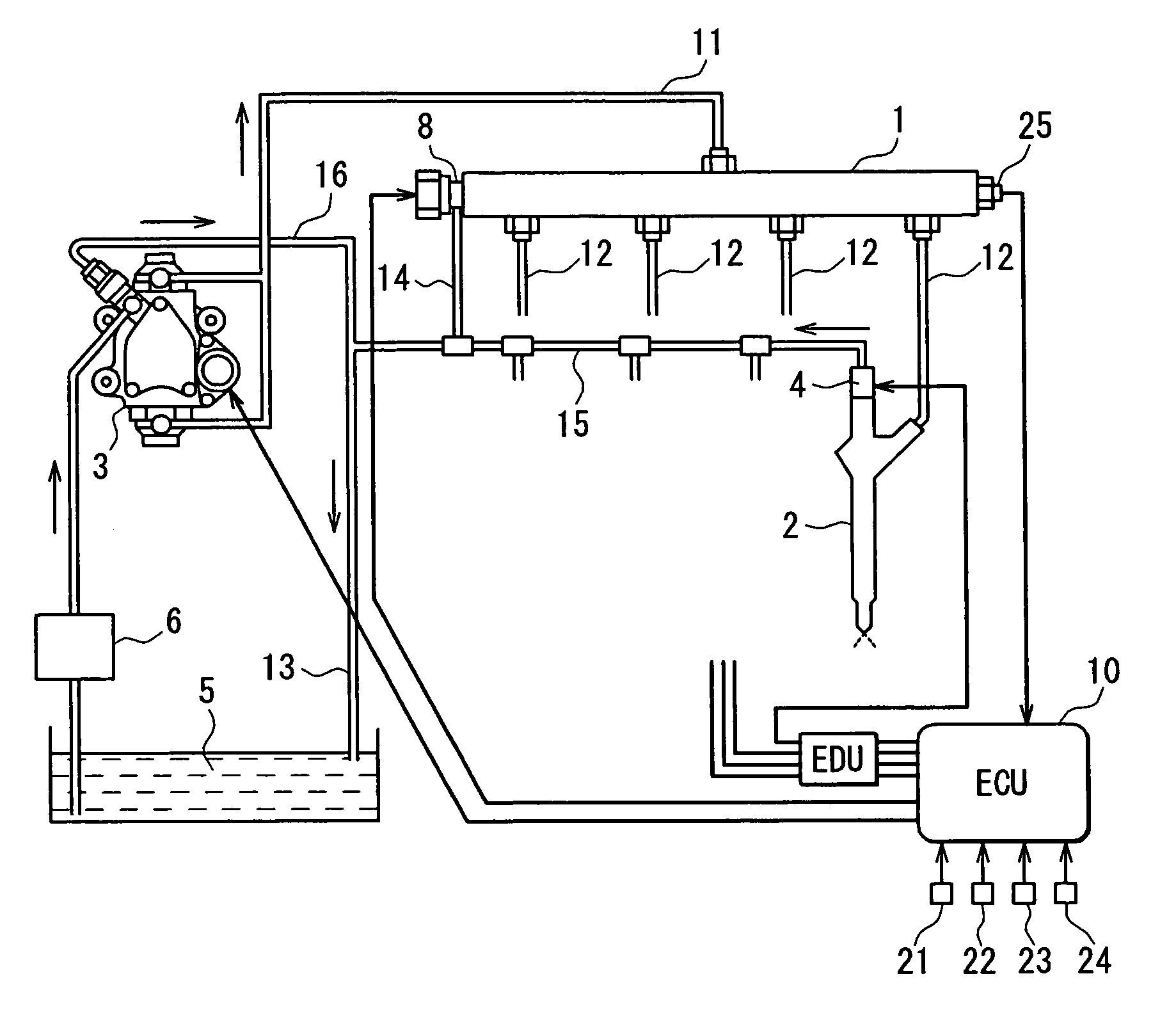
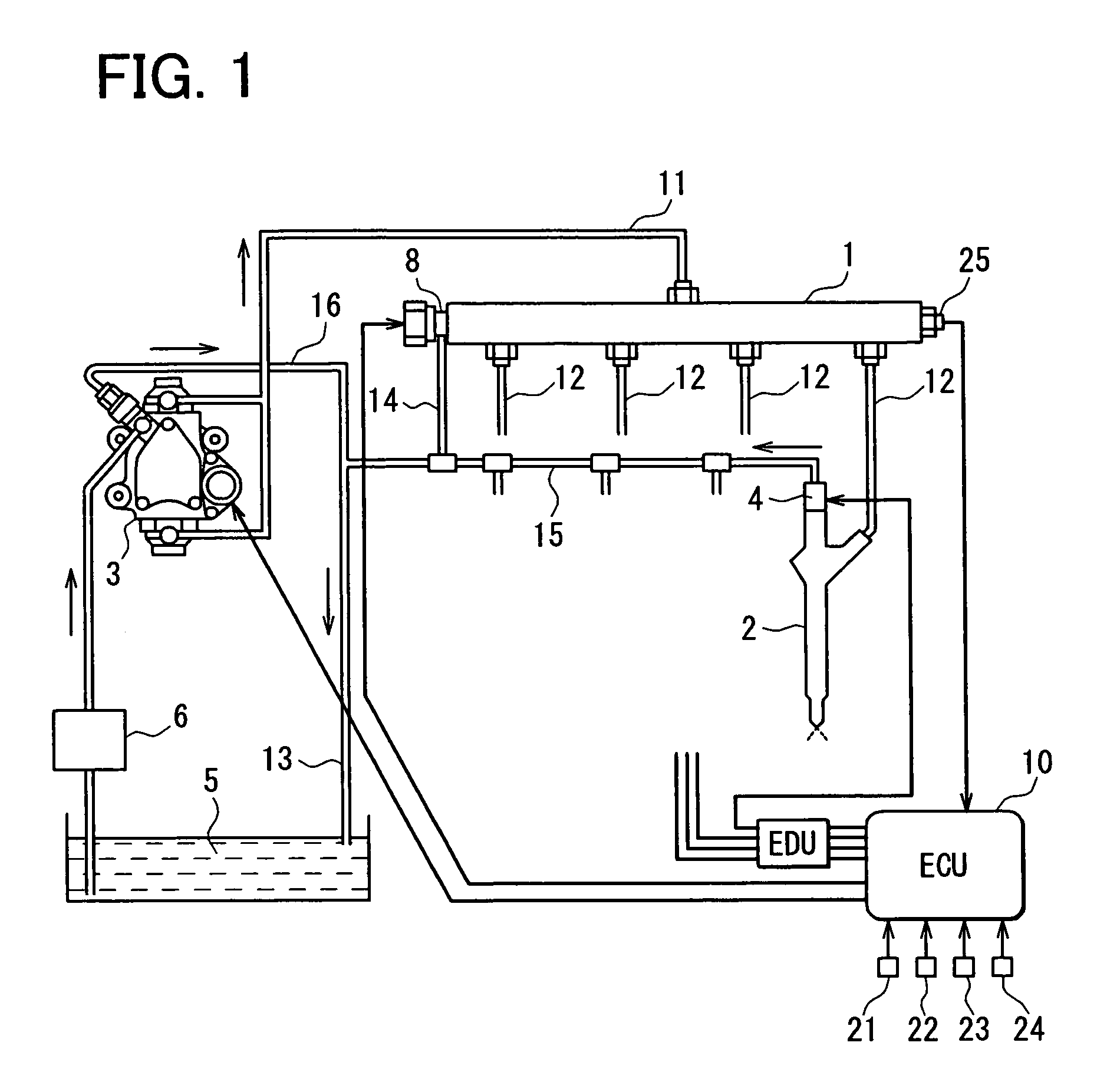
[0017]Referring to FIG. 1, a pressure accumulation fuel injection controller according to an example embodiment of the present invention is illustrated. The fuel injection controller has a pressure accumulation vessel (common rail) 1, multiple (four, in the present embodiment) fuel injection valves (injectors) 2, a fuel supply pump (supply pump) 3, and an electronic control unit (ECU) 10. The common rail 1 provides a pressure accumulation chamber for accumulating high-pressure fuel according to a fuel injection pressure. The multiple injectors 2 are connected with the common rail 1 and inject the fuel into respective cylinders of a four-cylinder engine such as a multi-cylinder diesel engine. The supply pump 3 is rotated and driven by the engine. The ECU 10 functions as a control section for electronically controlling the multiple injectors 2 and the supply pump 3.

[0018]The common rail 1 needs to continuously accumulate the high pressure corresponding to the fuel injection pressure. ...


PUM


Abstract

A pressure pattern estimation device of a fuel injection controller of an engine estimates a pressure transition of fuel in a common rail. A surplus pressure range calculation device of the fuel injection controller calculates a surplus pressure range in which pressure pattern data provided by the pressure pattern estimation device exceeds a target common rail pressure. The fuel injection controller releases the common rail pressure to a lower-pressure side by operating a pressure reduction valve of the common rail to eliminate the surplus pressure range calculated by the surplus pressure range calculation device. Thus, the common rail pressure (injection pressure) during an injection period is smoothed.

Description

CROSS REFERENCE TO RELATED APPLICATION[0001]This application is based on and incorporates herein by reference Japanese Patent Application No. 2005-208649 filed on Jul. 19, 2005.BACKGROUND OF THE INVENTION[0002]1. Field of the Invention[0003]The present invention relates to a pressure accumulation fuel injection controller used mainly in a diesel engine.[0004]2. Description of Related Art[0005]A pressure accumulation fuel injection device having a pressure accumulation vessel (common rail), a fuel injection valve (injector) and a suction metering fuel supply pump is known as a fuel injection device for a diesel engine. The pressure accumulation vessel accumulates high-pressure fuel according to a fuel injection pressure. The injector injects and supplies the high-pressure fuel in the accumulation vessel into each cylinder of the engine. The supply pump pressurizes the fuel suctioned into a pressurization chamber to high pressure and pressure-feeds the fuel to the pressure accumulatio...

Claims


Application Information

Patent Timeline
Patent Type & Authority Patents(United States)
IPC IPC(8): F02M37/04
CPCF02D41/3845F02M47/027F02M63/0225F02M63/025F02M63/04F02D2041/2027F02D2200/0602F02D2200/0604
Inventor NAKANE, NORIAKI
Owner DENSO CORP
Learn More