Cordless fastener driving tool

a technology of driving tool and fastener, which is applied in the direction of manufacturing tools, stapling tools, nailing tools, etc., can solve the problems of high cost of operating these tools, the need of pneumatic power of compressors, and the cost of pneumatic and electrical tools, and achieve the effect of efficient driving small gauge fasteners into workpieces

Active Publication Date: 2007-04-10
KYOCERA SENCO IND TOOLS INC
View PDF11 Cites 16 Cited by
  • Summary
  • Abstract
  • Description
  • Claims
  • Application Information

AI Technical Summary

Benefits of technology

[0011]It is therefore an object to the present invention to provide a fastener driving tool of simple construction which is compact and reliable.
[0013]It is a still further object of the present invention to provide a fastener driving tool which uses stored energy to efficiently drive small gauge fasteners into a workpiece.

Problems solved by technology

While these tools work well, one drawback to their use is the requirement of a compressor to provide the pneumatic power.
Although this type of tool has been successful, some drawbacks have been associated with internal combustion tools.
First, the expense for operating these tools is higher than the pneumatic and electrical tools; in addition, the exhaust fumes from these tools can be bothersome when working in an enclosed area.
However, these tools are necessarily bulky and heavy, as they require high energy mechanisms to drive the fasteners.
These springs do not adapt efficiently in a chamber to create a sufficient force to drive larger fasteners, and the springs generally do not have proper duty cycles, leading to premature failure.

Method used


Image

  • Cordless fastener driving tool
  • Cordless fastener driving tool
  • Cordless fastener driving tool

Examples


Embodiment Construction

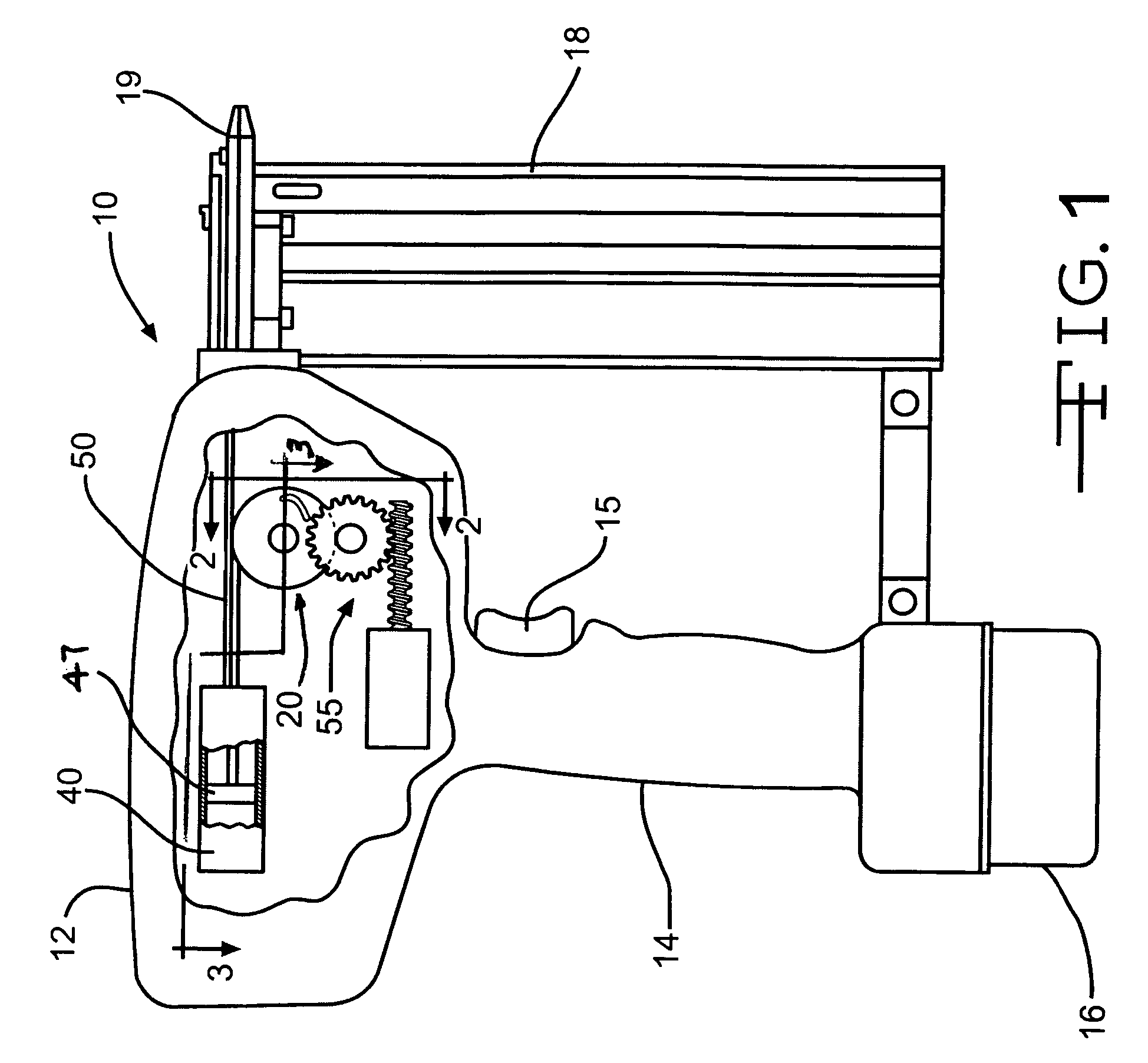
[0028]FIG. 1 illustrates a typical battery powered hand held fastener driving tool generally indicated at 10 comprising a main body or housing 12, handle 14 including activation trigger 15, a battery pack 16, and a fastener magazine 18 including a typical guide body 19. Main body 12 is shown having a portion of its side removed, thereby showing the general arrangement of the principal subassemblies of the tool's working mechanism in accordance with the present invention.

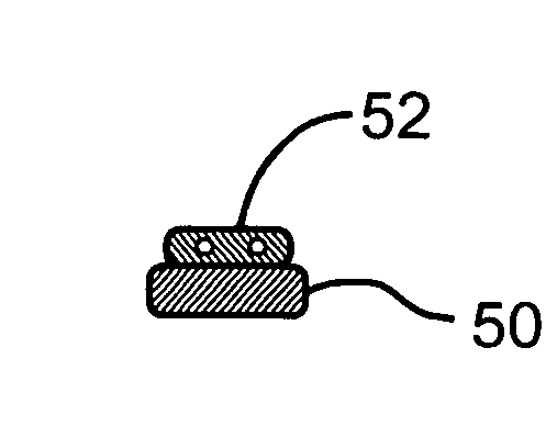
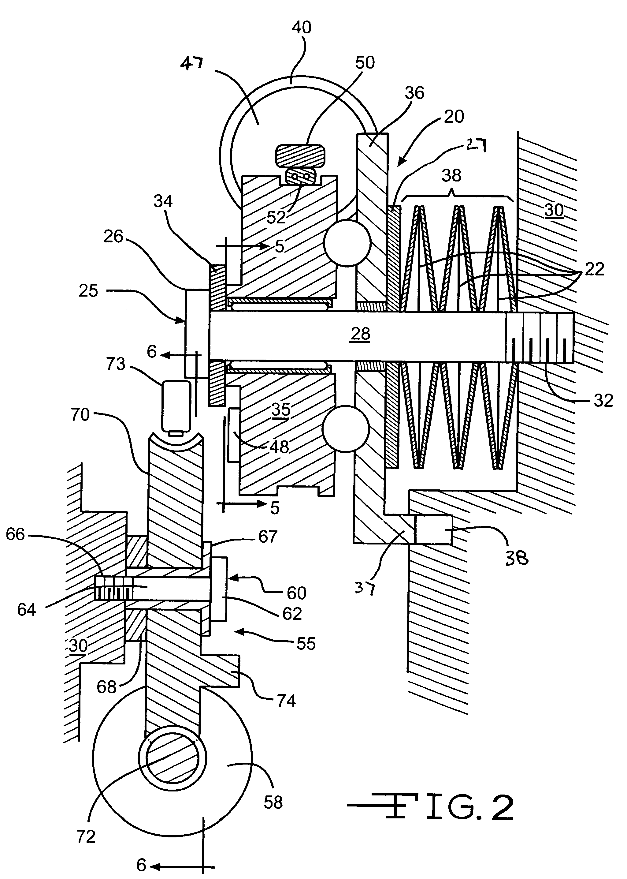
[0029]Referring now to FIGS. 2 and 3, the primary working mechanism comprises two major subassemblies, a fastener driving subassembly generally indicated at 20, and a motor / gear subassembly generally indicated at 55.

[0030]Fastener driving subassembly 20 comprises a central axial pin indicated at 25 having a head end 26 and an elongated shaft portion 28 rigidly affixed to a frame 30 of tool main body 12 by screw threads 32, or any other convenient means.

[0031]Assembled coaxially upon axial pin 25, between pin head end...


PUM


Abstract

The present invention teaches a unique drive mechanism for use in a hand held fastener driving tool. The driving mechanism comprises a pair of opposing cams coaxially positioned upon a common shaft. One of the cams is motor driven and rotatable about the common shaft but not axially translatable while the other cam is axially translatable but non-rotatable. Rotation of the rotatable cam by the motor causes the non-rotatable axially translatable cam to compress a compressible spring assembly, storing potential energy therein. Simultaneously, a driver activation cable, wrapped about the rotatable cam's periphery, unwraps thereby raising a fastener driver to its driving configuration. Upon release of the rotatable cam from the motor drive, the potential energy stored within the spring assembly causes reverse rotation of the rotatable cam thereby rewinding the drive cable about the rotatable cam's periphery and driving the fastener driver, whereby the driver drives a fastener into a workpiece.

Description

CROSS REFERENCE TO RELATED APPLICATIONS[0001]This application claims benefit from U.S. Provisional Patent Application Ser. No. 60 / 567,263, filed Apr. 30, 2004, which application is incorporated herein by reference.BACKGROUND OF THE INVENTION[0002]1. Field of the Invention[0003]This invention relates generally to fastener driving tools, in particular, to a battery operated fastener driving tool which uses the energy stored in a spring to drive the fastener.[0004]2. Description of the Related Art[0005]Many different types of tools have been developed over the years for the purpose of driving a fastener into wood. The most common type of fastener driving tool is the type in which the driver is actuated pneumatically. An example of this type of tool is shown in U.S. Pat. No. 3,278,106. While these tools work well, one drawback to their use is the requirement of a compressor to provide the pneumatic power.[0006]In recent times, other designs for fastener driving tools have used electrome...

Claims


Application Information

Patent Timeline
Patent Type & Authority Patents(United States)
IPC IPC(8): B25C1/06B25C1/18B25C1/12B25C1/00
CPCB25C1/06
Inventor LEIMBACH, RICHARD L.
Owner KYOCERA SENCO IND TOOLS INC
Why Eureka
Try Eureka