
Signaling safety system

a safety system and signal technology, applied in the direction of vehicle position/course/altitude control, process and machine control, instruments, etc., can solve the problems of inability to maintain communication quality above a fixed level, inability to maintain system operation rate, etc., to improve the operation rate, improve the effect of safety control, and improve the effect of communication quality

Active Publication Date: 2007-04-10
HITACHI LTD
View PDF14 Cites 38 Cited by
  • Summary
  • Abstract
  • Description
  • Claims
  • Application Information

AI Technical Summary

Benefits of technology

The present invention provides a signaling safety system that can operate even when there is a failure in radio communication. The system uses ground-train communication by radio to communicate the position of each train to the ground equipment, which then sends information regarding speed restrictions to the on-train device of each train. The system also uses additional communication devices installed on the ground and train to switch from operation of ground-train communication by radio to operation using communication between the additional communication devices when the ground equipment fails. This backup system ensures confirmation of train presence on-rail and safety control, even when there is a failure in an essential section of the backup system. The system also enables quick confirmation of incoming and outgoing in the station yard and improves safety.

Problems solved by technology

Because radio is used as the communication medium, the effects of unavoidable interference such as disturbing radio waves and environmental changes, make it difficult always to maintain the communication quality above a fixed level.
When such communication quality is not maintained, compared with the conventional track circuit system, the operation rate of the system is inevitably reduced.

Method used


Image

  • Signaling safety system
  • Signaling safety system
  • Signaling safety system

Examples


Embodiment Construction

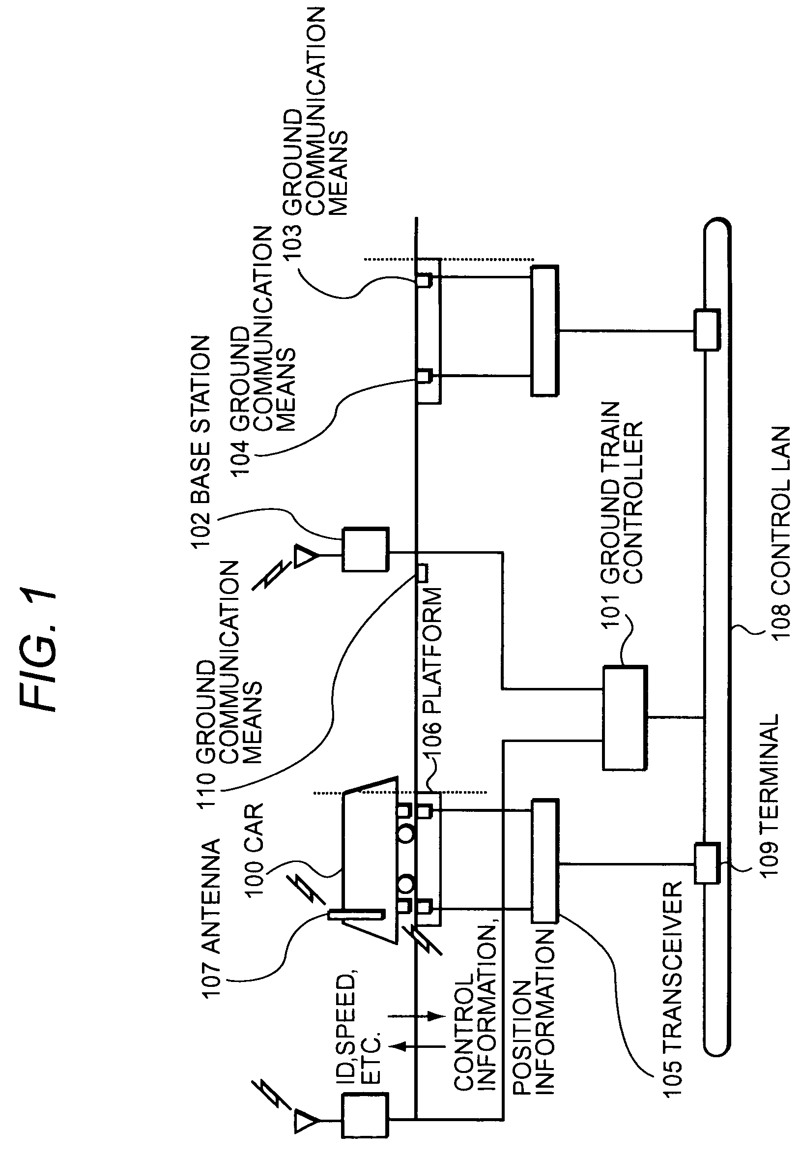
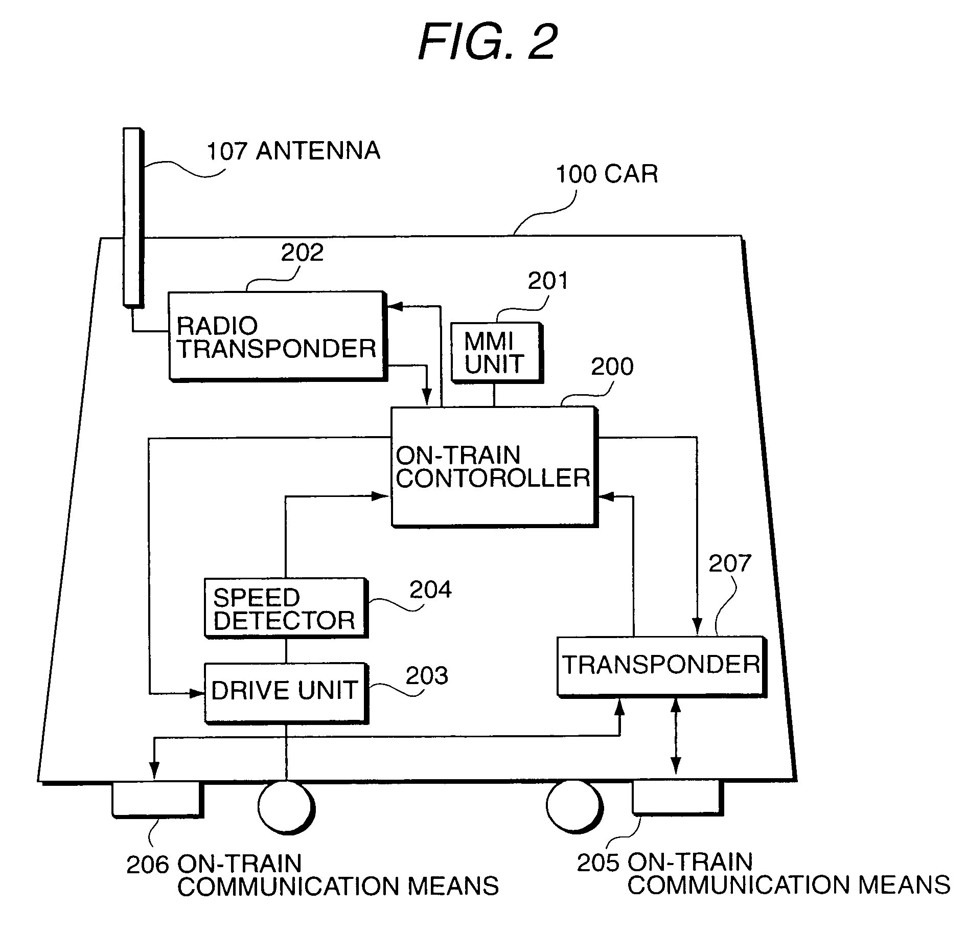
[0036]An embodiment of the present invention will be explained below with reference to FIGS. 1 to 18.

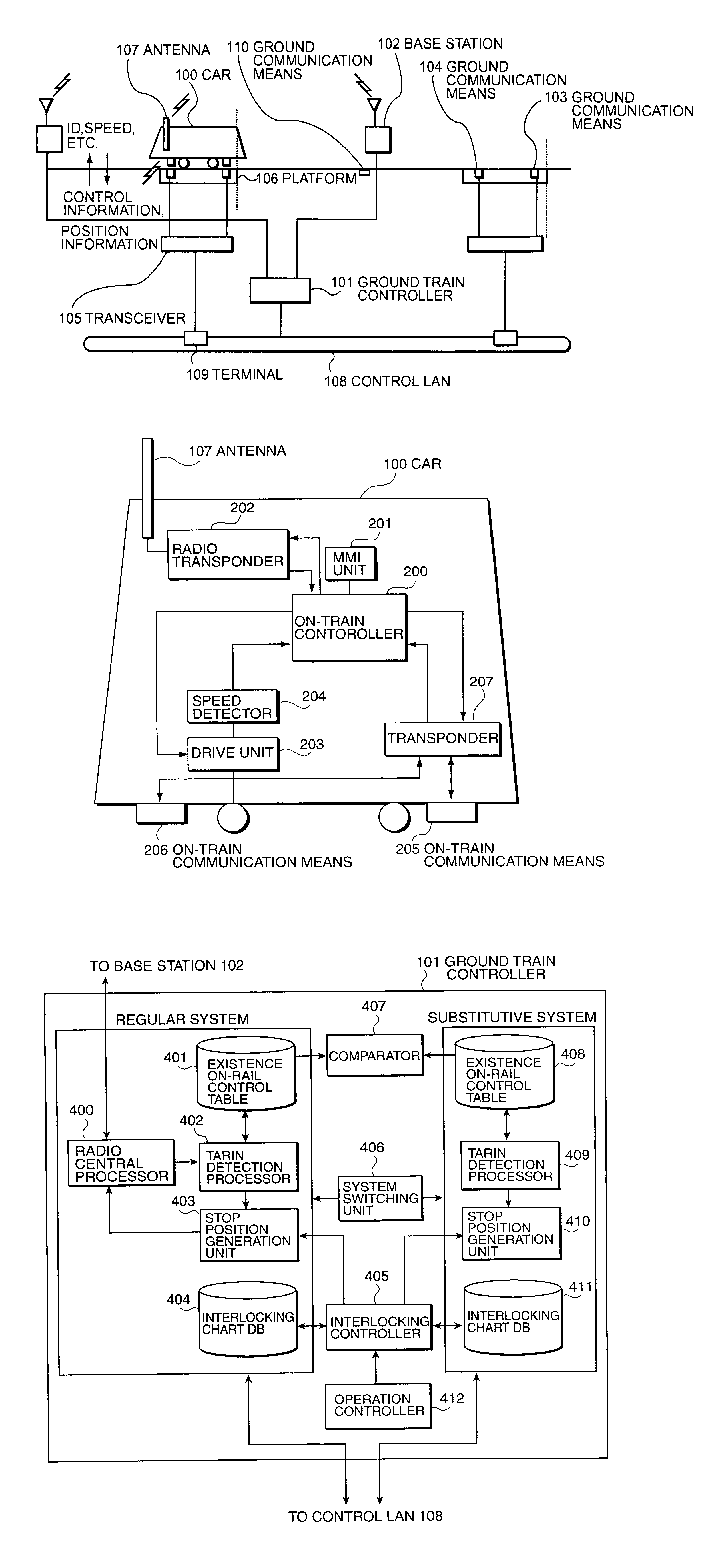
[0037]Firstly, the signaling safety system of the present invention will be explained. The whole schematic system configuration as an example is shown in FIG. 1. As shown in FIG. 1, the system is composed of a car 100 to be controlled, a ground train controller (equivalent to a main ground device) 101 which is a central processor on the ground side, a (radio) base station 102, ground communication means (communication devices relating to the present invention equivalent to two-way balises) 103 and 104 which are narrow-area (less than 1 m) radio communication means, a transponder 105, an antenna 107, a control LAN 108, a terminal 109, and a ground communication means (single-way balise) 110.

[0038]Among them, the radio communication means (installed at least on a platform 106 of each station) 103 and 104 are connected to the ground train controller 101 via the transponder 105 and the t...


PUM


Abstract

A signaling safety system includes transmitter-receiver units for ground-train communication by radio in regular safety operation mode, using a base station and an antenna. The position of each train car is communicated from the cars to a ground train controller which detects the presence of a train on-rail. Based on the latter information, information is transmitted from the controller to each of the cars regarding corresponding speed limits. In addition to such radio transmitter-receivers, the signaling safety system also includes additional communication devices, such that, when each of the cars approaches a specific range, car information from each of the cars can be received by the controller, by communication between ground communication devices and an on-train communication device which are installed so as to communicate with each other. Concurrently with the regular safety operation, by the alternative safety system, the presence on-rail of each of the cars is controlled for each new block section. When ground-train communication by radio fails, the controller switches to operation by the alternative safety system so that safe operation of the train can be continued.

Description

BACKGROUND OF THE INVENTION[0001]1. Field of the Invention[0002]The present invention relates to a signaling safety system for a transit system moving on a track, such as railroads, monorails, and LRT (light rail transit: next generation streetcar). More particularly, the invention provides a signaling safety system that is operable when each train approaches a specific range, using radio communication devices that are installed respectively on the ground and train. When ground communication by radio cannot be used, the invention provides for switching from operation via ground-train radio communication to the operation by additional communication devices.[0003]2. Description of the Related Art[0004]In a conventional railroad signaling safety system, train detectors called track circuits are installed on all tracks and are used to confirm the presence of a train on-rail. However, installation expenses of track circuits and maintenance expenses are enormous, so that a railroad system...

Claims


Application Information

Patent Timeline
Patent Type & Authority Patents(United States)
IPC IPC(8): G05D1/00B61L3/12B61L3/22B61L23/14B61L23/16B61L27/00
CPCB61L3/125B61L27/0077B61L27/0038B61L23/14B61L27/20B61L27/40
Inventor SUGITA, YOICHIWATANABE, DAIAKIYAMA, MASAKAZU
Owner HITACHI LTD
Learn More