

Ink jet printing apparatus and method for correcting ejection driving
a printing apparatus and ink jet technology, applied in the direction of printing, electrical apparatus, pictoral communication, etc., can solve the problems of affecting the image quality of the dots to be printed by the nozzle, the failure of the conventional printing apparatus described above, and the noticeable degradation of the image quality
- Summary
- Abstract
- Description
- Claims
- Application Information
AI Technical Summary
Benefits of technology
Problems solved by technology
Method used
Image

Examples
fourth embodiment
[Second, Third and Fourth Embodiment]
[0118]In the first embodiment, a Y deviation value of each ink dot is used as an important parameter in setting nozzle profile information. The present invention can also use other values in addition to the Y deviation value as the parameter.
[0119]For example, in a second embodiment of this invention shown in FIG. 12, a dot diameter in addition to the Y deviation value of a faulty nozzle is used as the parameter, as shown at step S13. Further, in a third embodiment of the present invention shown in FIG. 13, an X deviation value in addition to the Y deviation value and dot diameter is used as the parameter, as shown at step S23. Further, in a fourth embodiment of the present invention shown in FIG. 14, a dot shape in addition to the Y deviation value, dot diameter and X deviation value is used as the parameter, as shown at step S33.
[0120]Setting as many parameters as possible, as described in the second to fourth embodiments, can produce more prec...
example 1
[0122]Next, some examples of printing performed by using the ink jet printing apparatus and the printing method according to the first embodiment of the invention will be explained.
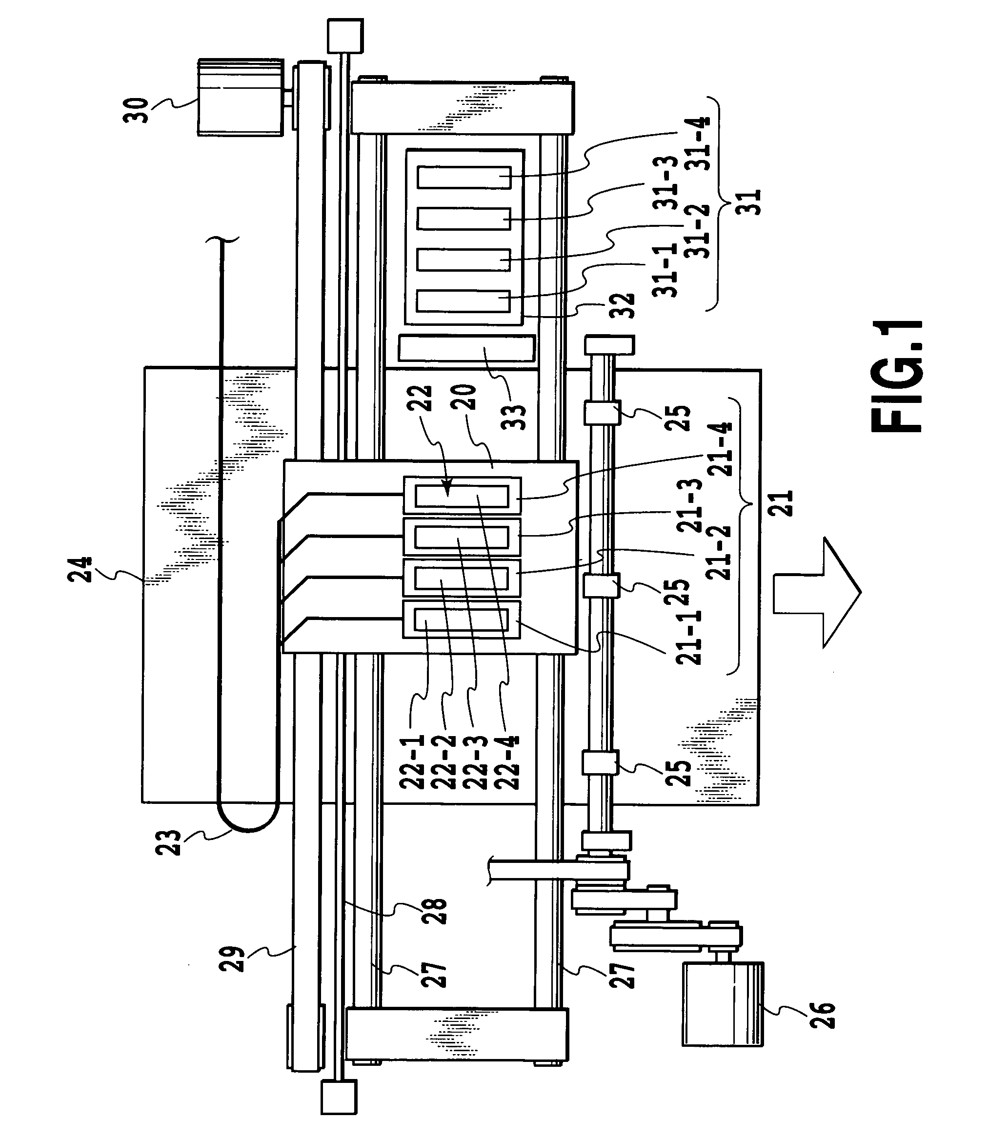
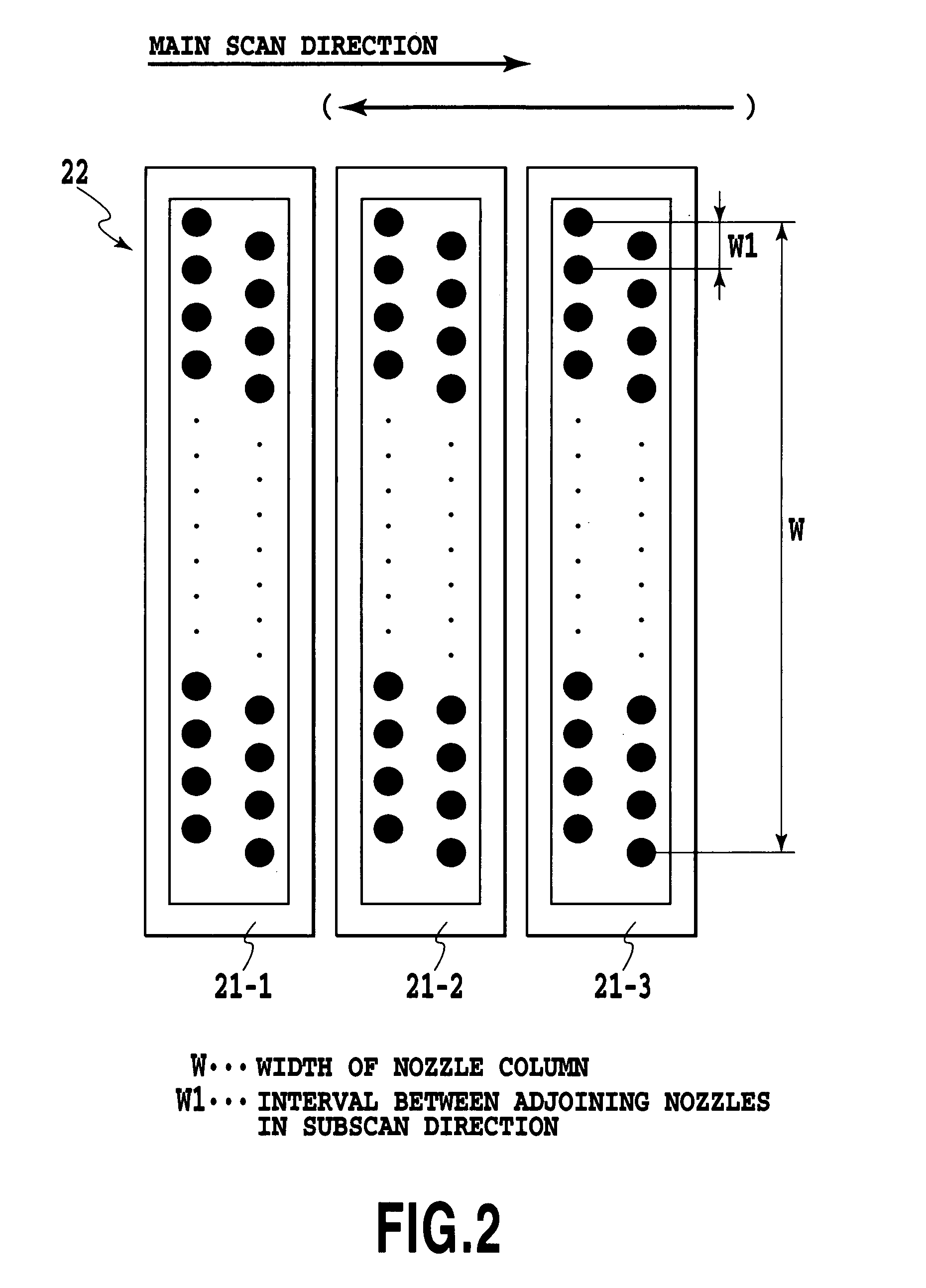
[0123]A print head used has a resolution of 1,200 dpi and an array of 4,096 nozzles, with an ink ejection volume (volume of each ink droplet) set to 4.5±0.5 pl.
[0124]Inks containing colorants have the following compositions.
[0125]
(Prescription: Y ink)Glycerine5.0 parts by weightThiodiglycol5.0 parts by weightUrea5.0 parts by weightIsopropyl alcohol4.0 parts by weightDystuff, C.I. Direct Yellow 1422.0 parts by weightWater79.0 parts by weight (Prescription: M ink)Glycerine5.0 parts by weightThiodiglycol5.0 parts by weightUrea5.0 parts by weightIsopropyl alcohol4.0 parts by weightDystuff, C.I. Acid Red 2892.5 parts by weightWater78.5 parts by weight (Prescription: C ink)Glycerine5.0 parts by weightThiodiglycol5.0 parts by weightUrea5.0 parts by weightIsopropyl alcohol4.0 parts by weightDystuff, C.I. Direct B...
example 2
[0161]Next, Example 2 of a printing operation performed by the ink jet printing apparatus and the printing method of the fifth embodiment of this invention will be described in the following.
[0162]A print head, as in the previous Example 1, has 4,096 nozzles arranged at a resolution of 1,200 dpi, with a single ink ejection volume (volume of an ink droplet) set to 4.5±0.5 pl. Compositions of inks containing colorants are the same as those in Example 1.
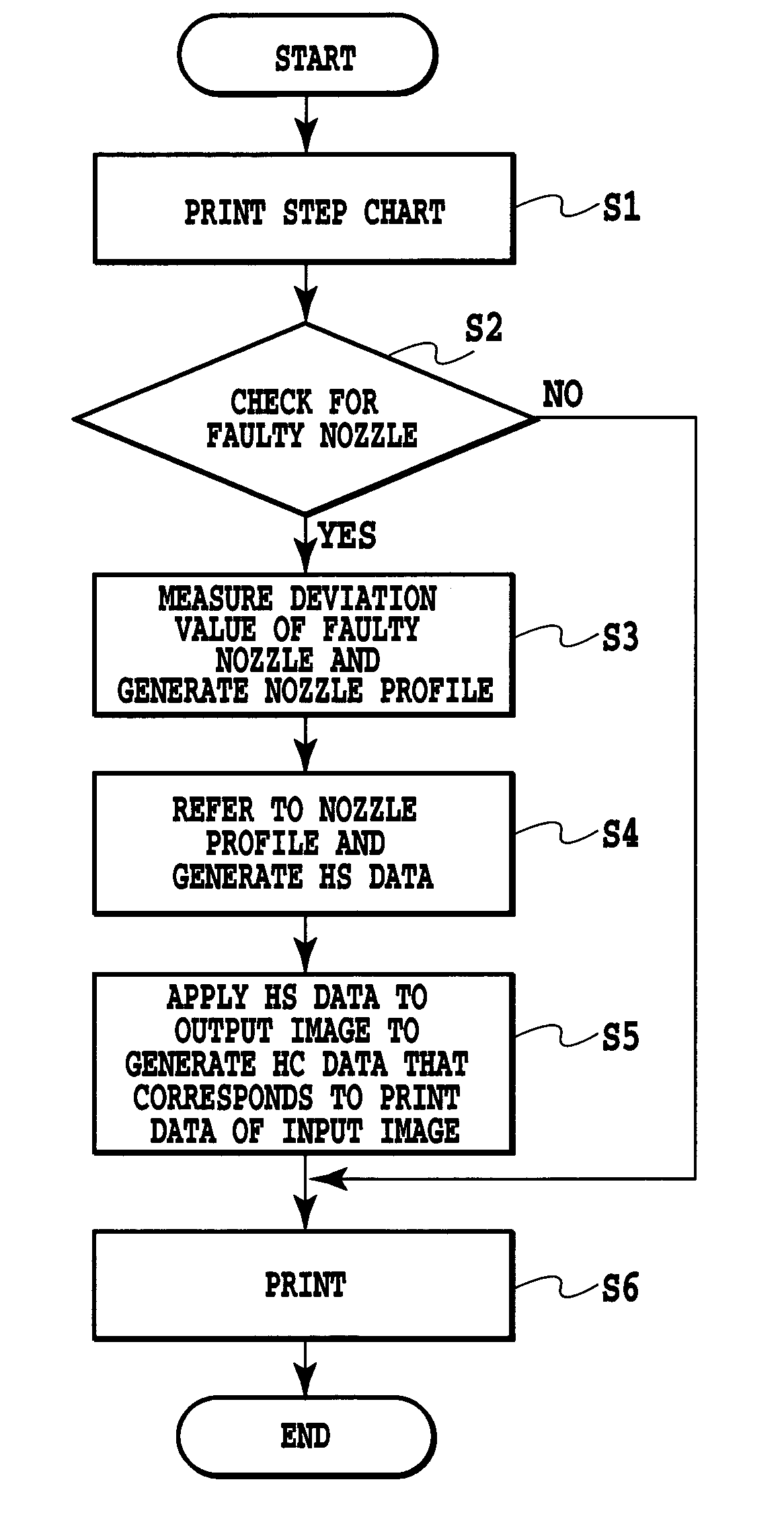
[0163]A printing operation control was performed according to a sequence shown in the flow chart of FIG. 16.
[0164]First, a step chart of FIG. 4 was output and the printed step chart was measured by an optical sensor (scanner) not shown at a resolution of 4,800 dpi. Individual line segments of the step chart were subjected to line-thinning processing to determine gravity centers of ink dots and thereby measure Y deviation values of ink dots from ideal dot landing positions. At the same time, a solid printed chart was also read to determi...
PUM
 Abstract
Description
Claims
Application Information