Cable arrangement for robot arm, and industrial robot utilizing the same

a robot arm and cable technology, applied in the direction of programmed manipulators, manufacturing tools, welding apparatus, etc., can solve the problems of limited operability or movable range of welding torch cables, difficult to handle, and wear of torch cable cables, so as to prolong the life of the robot, minimize the influence of bending operation, and excellent welding torch mobility

Active Publication Date: 2007-04-10
DAIHEN CORP
View PDF17 Cites 60 Cited by
  • Summary
  • Abstract
  • Description
  • Claims
  • Application Information

AI Technical Summary

Benefits of technology

[0023]According to the present invention, the following advantages are enjoyed.
[0034]The present invention is advantageously applied to a multi-joint robot, in particular, a 6-axis manipulator. In this instance, the present invention may preferably be applied to the cable arrangement between the fourth shaft and the fifth shaft of the manipulator. In this manner, it is possible to minimize the influence of the bending operation (repetitive bending or holding the bent state) at the fifth shaft on the upstream portions (i.e., toward the fourth shaft) of the torch cable. As a result, excellent mobility of the welding torch (which means a greater coverage of operation areas, higher operational efficiency, etc.) is ensured, and meanwhile the feeding of the welding wire can be performed properly. Thus, high-quality welding will result, and a prolonged life of a conduit is expected.

Problems solved by technology

Because of the multi-layer structure, the torch cable tends to be rigid and therefore is difficult to handle.
In operating a welding robot, the operability or movable range of the welding torch is limited by the length and flexibility of the torch cable, for example.
As is often the case, the torch cable can be worn out in repeated bending action of the arm, which is a problem of the prior art.
Another problem is that when the welding arm in motion comes to a sudden stop, for instance, the torch cable tends not to stop together with the welding arm, but continues to swing due to its inertia.
Such undesired movement disturbs smooth feeding of the welding wire through the conduit pipe.
Further, the conventional torch cable arrangement causes the following problem.
When a welding robot is operated with other robots, jigs, etc. placed around, or is used for welding an area inside of a container (which may be cylindrical or box-like, for example), the torch cable may come into direct interference with the things around or the side walls of the container, which results in poor operation efficiency and poor quality of products.
However, such an idea can only hold true when the multi-joint robots use their joints primarily in rotating or twisting movements but not much for swinging or tilting movements.
The arrangement is not always ideal when the multi-joint robot has to work with much bending operation, or keep a bending attitude.
The rubbing location changes as the curvature varies, and the friction force acting between the conduit pipe and the filler wire varies as the conduit pipe deforms, which results in unstable feeding speed.
This results in undesirable variation in the amount of wire supply, disturbing the welding arc, making impossible to achieve significant improvement in the welding quality.

Method used


Image

  • Cable arrangement for robot arm, and industrial robot utilizing the same
  • Cable arrangement for robot arm, and industrial robot utilizing the same
  • Cable arrangement for robot arm, and industrial robot utilizing the same

Examples


Embodiment Construction

[0051]Hereinafter, a cable arrangement for a robot arm and an industrial robot employing such a cable arrangement will be described with reference to the accompanying drawings.

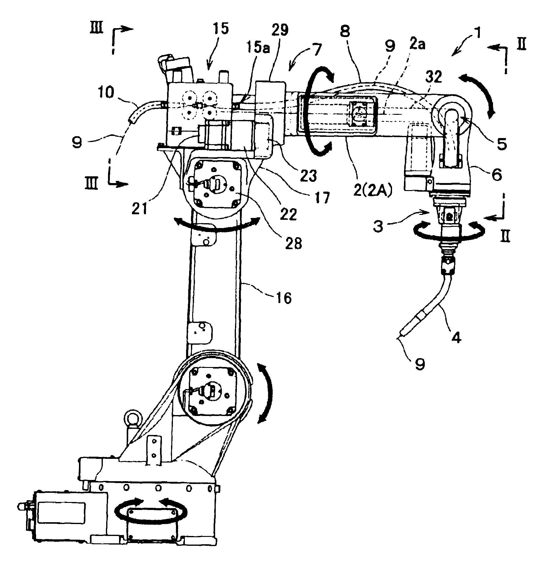
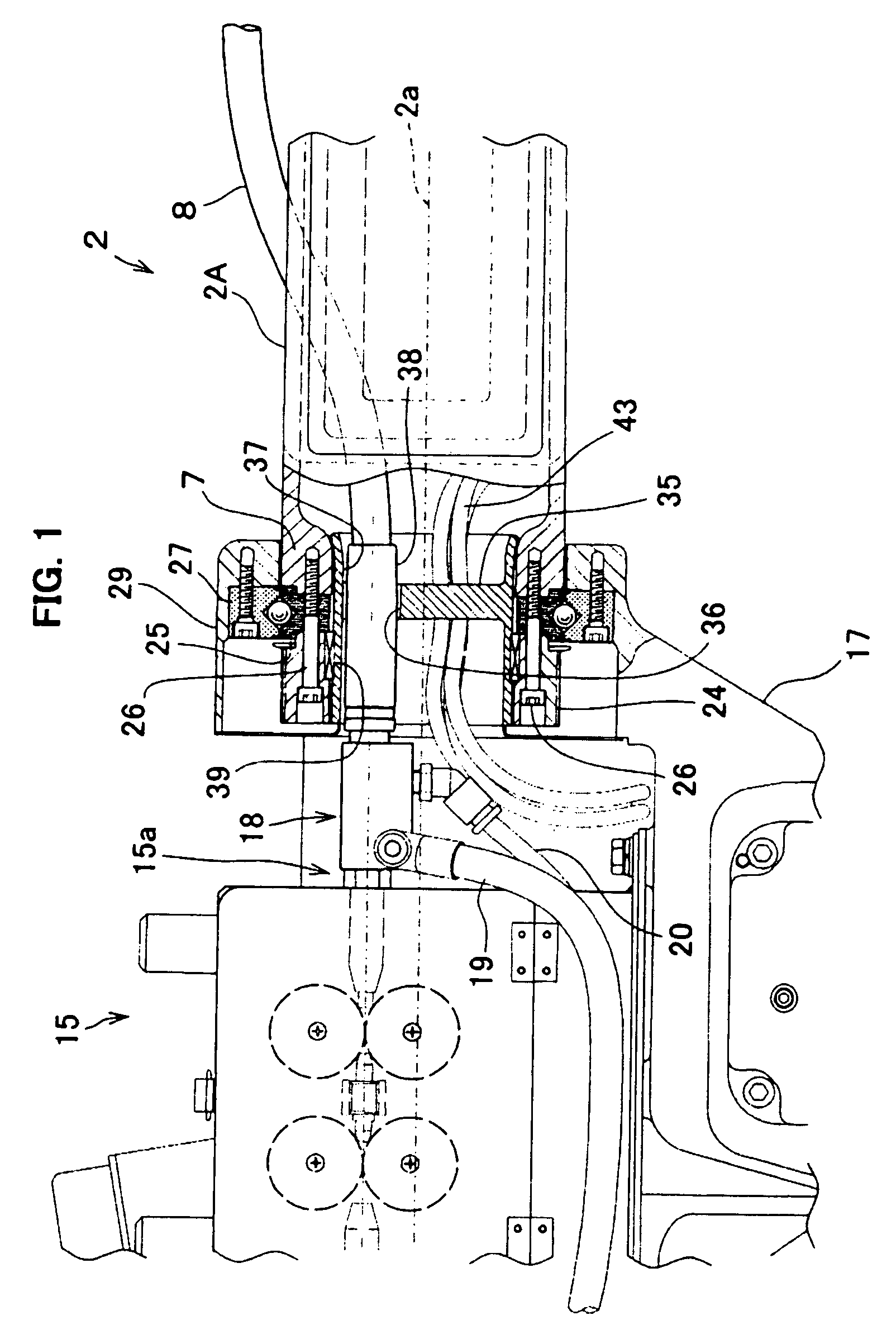
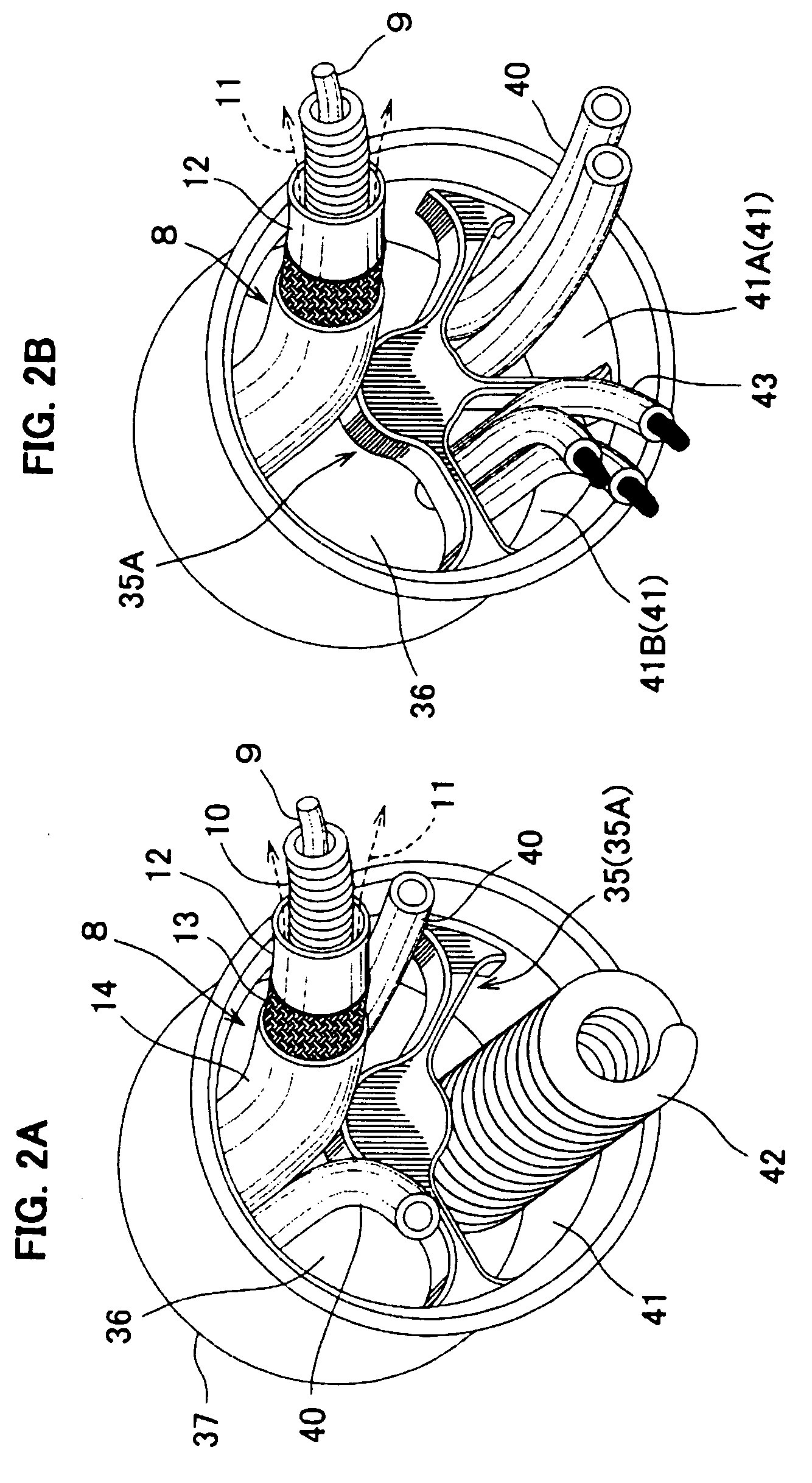
[0052]Reference is first made to FIGS. 4A–4B and 5A–5B showing a multi-joint arc-welding robot 1 to which the present invention is applied. FIG. 4A is a front view of the robot, FIG. 4B is a sectional view taken in lines II-II in FIG. 4A, FIG. 5A is a sectional view taken in lines III-III in FIG. 4A, and FIG. 5B is a plan view of the robot. Aside from FIG. 5A, all of the figures show an upper arm 2 (to which the present invention is applied), illustrating its shape and the way it is attached. FIGS. 3A, 3B are a plan view and a front view illustrating how cables are arranged in the upper arm 2.

[0053]The arc-welding robot 1 includes six joints for implementing the movements indicated by the arrows in FIG. 4A. Each joint provides for implementing a rotating or twisting movement required for the arm to rotate, piv...


PUM

PropertyMeasurementUnit
electric energyaaaaaaaaaa
pressureaaaaaaaaaa
movementaaaaaaaaaa

Abstract

A cable arrangement for a robot arm is provided, which includes a rotation arm and a line member such as a power cable. The rotation arm has a front end and a base end, the front end being provided with a swing shaft, the base end being provided with a rotational shaft rotatable about a longitudinal axis. The line member extends from the base end toward the front end of the arm. The rotational shaft includes a line offset member formed with at least one through-hole for passing the line member. The through-hole as a whole is offset from the axis of the rotational shaft.

Description

BACKGROUND OF THE INVENTION[0001]1. Field of the Invention[0002]The present invention relates to an arrangement for a cable or any other line member with respect to a robot arm. The present invention also relates to an industrial robot to which such a cable arrangement is applied.[0003]2. Description of the Related Art[0004]Arc-welding robots are equipped with a welding wire feeder so that supplementary filler wire (consumable electrode), unwound from a wire reel, is fed to the welding torch. At the torch, the wire is melt with electric energy to perform welding continuously. The wire feeder is provided with presser rollers for forwarding the filler wire under pressure to the welding torch.[0005]Arc-welding robots typically have multiple joints. For example, the entire arm mechanism includes a total of six joints, namely, first through sixth joints, and these joints are individually operated for causing the operational arm to rotate, swing, pivot or tilt. As a result, the end effect...

Claims


Application Information

Patent Timeline
Patent Type & Authority Patents(United States)
IPC IPC(8): B23K9/32B23K9/12B23K9/133B25J19/00
CPCB25J19/0029B25J19/00B25J9/06
Inventor NAKAGIRI, HIROSHIMIYAHARA, HISAO
Owner DAIHEN CORP
Why Eureka
Try Eureka