Method and apparatus for decoding sync marks in a disk

a technology of disk drive and sync mark, applied in the field of disk drive, can solve the problems of more prone to detection error than the first sync mark, second sync mark is problematic, and data detection error, and achieve the effect of increasing the error ra

Inactive Publication Date: 2007-04-10
KK TOSHIBA
View PDF7 Cites 135 Cited by
  • Summary
  • Abstract
  • Description
  • Claims
  • Application Information

AI Technical Summary

Benefits of technology

[0018]In accordance with an embodiment of the present invention, there is provided a disk drive that includes means for recording sync marks that can be detected at high probability and does not increase the error rate in reproducing the user data that follows the sync marks.

Problems solved by technology

As a result, any signal reproduced changes in amplitude, very likely to cause an error in the detection of data.
The second sync mark is more liable to detection error than the first-sync mark, due to the shifting of the base line.
To the read channel having low-band cutoff characteristic, the second sync mark is problematical, because its bit pattern is a series of “0s” and “1s” that are in accordance with the NRZ (non-return to zero) rule.
Consequently, the disk drive may fail to detect the first several bits of the user data, which immediately follow the second sync mark.

Method used


Image

  • Method and apparatus for decoding sync marks in a disk
  • Method and apparatus for decoding sync marks in a disk
  • Method and apparatus for decoding sync marks in a disk

Examples


Embodiment Construction

[0033]Embodiments of this invention will be described, with reference to the accompanying drawings.

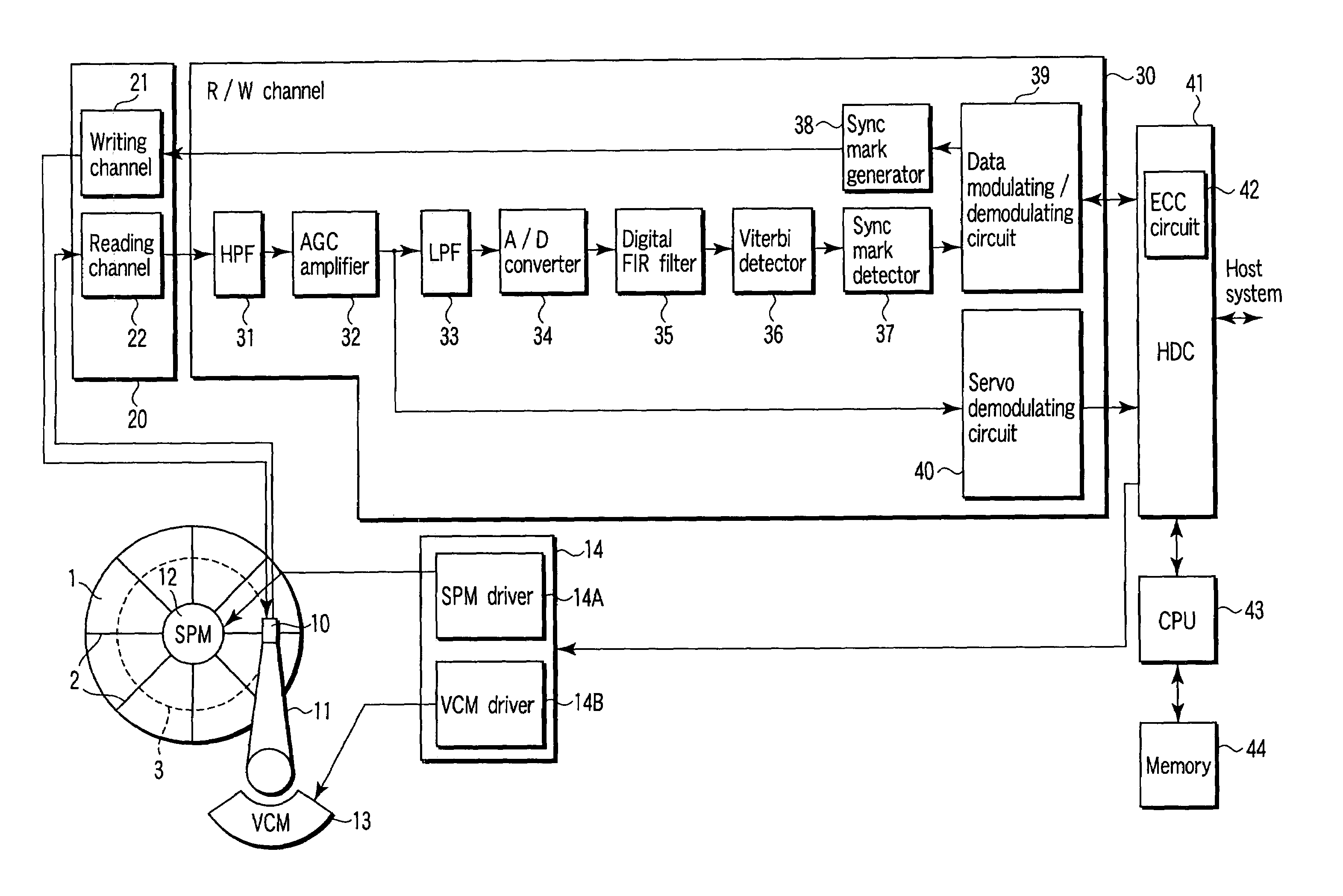
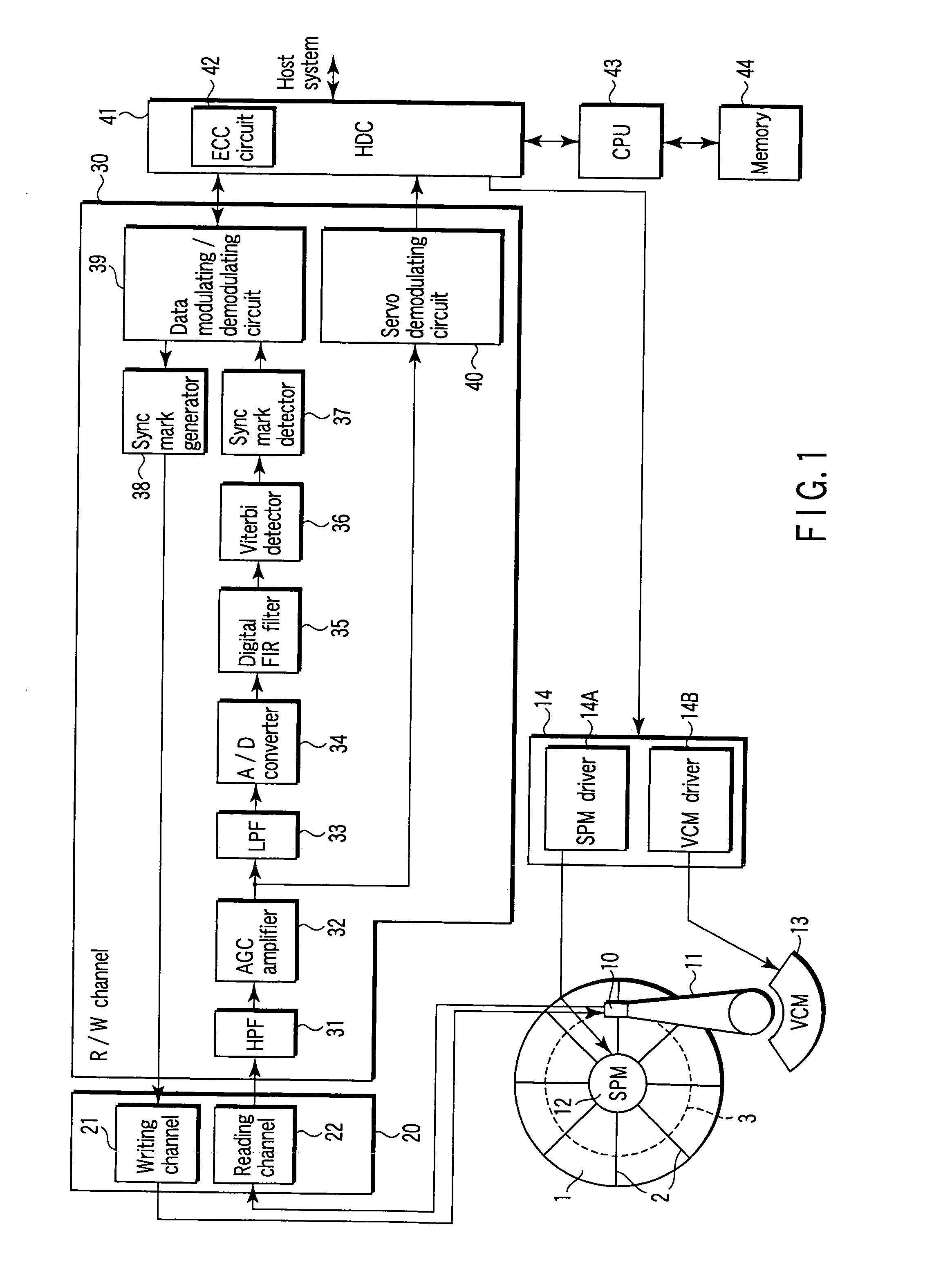
[0034]FIG. 1 is a block diagram showing the major components of a disk drive according to a first embodiment of the invention.

[0035](Configuration of the Disk Drive)

[0036]The disk drive according to the embodiment is a perpendicular magnetic recording device. As FIG. 1 shows, it comprises a disk 1, a spindle motor (SPM) 12, a head 10, a drive mechanism, and a control / signal-processing circuit system. The disk 1 exhibits magnetic anisotropy perpendicular to its surfaces. The SPM 12 rotates the disk 1. The head 10 includes a write head and a read head. The write head can perform perpendicular magnetic recording. The read head comprises a giant magnetoresistive (GMR) element. The actuator holds the head 10 and moves the head 10 over the disk 1 in a radial direction thereof.

[0037]The actuator comprises an arm 11 and a voice coil motor (VCM) 13. The arm 11 holds the head 10 and includes a s...


PUM

PropertyMeasurementUnit
magnetization polarityaaaaaaaaaa
magnetizationaaaaaaaaaa
Tmaaaaaaaaaa

Abstract

In a disk drive that performs perpendicular magnetic recording, the read / write channel has a sync mark generator. The sync mark generator generates a second sync mark before the read / write channel operates to write data on a disk. The second sync mark has a bit pattern including a series of bits representing positive polarity and a series of bits representing negative polarity. The series of bits, which is longer than the other, has a bit length that is at least 50% but less than 85% of the total bit length of the second sync mark.

Description

CROSS-REFERENCE TO RELATED APPLICATIONS[0001]This application is based upon and claims the benefit of priority from prior Japanese Patent Application No. 2003-204387, filed Jul. 31, 2003, the entire contents of which are incorporated herein by reference.BACKGROUND OF THE INVENTION[0002]1. Field of the Invention[0003]The present invention relates to a disk drive that performs perpendicular magnetic recording. More particularly, the invention relates a technique of writing sync marks in the data sectors of a disk.[0004]2. Description of the Related Art[0005]In most disk drives, a representative example of which is a hard disk drive, user data supplied from a host system (e.g., a personal computer) are divided into 4096-bit (512-byte) data blocks. The data blocks iare recorded in the recording region of a disk-shaped recording medium (hereinafter called “disk”). The recording region of the disk is managed in units of so-called data sectors. Each data block (i.e., part of the user data)...

Claims


Application Information

Patent Timeline
Patent Type & Authority Patents(United States)
IPC IPC(8): G11B5/09G11B5/00G11B5/012G11B5/02G11B20/10G11B20/12G11B20/14G11B27/30
CPCG11B5/012G11B5/09G11B20/10009G11B27/3027G11B2005/001G11B2005/0016G11B2005/0029G11B2220/20
Inventor SAKAI, YUJISHIMOMURA, KAZUHITO
Owner KK TOSHIBA
Why Eureka
Try Eureka