Biaxial and shear testing apparatus with force controls

a testing apparatus and control technology, applied in the direction of apparatus for force/torque/work measurement, instruments, tension measurement, etc., can solve the problems of complex mechanical responses, inability to apply non-orthogonal biaxial loading, and inability of apparatuses with the combined feature of in-plane shear and compression/tension testing capabilities

Inactive Publication Date: 2007-04-17
NAVY UNITED STATES OF AMERICA
View PDF10 Cites 57 Cited by
  • Summary
  • Abstract
  • Description
  • Claims
  • Application Information

AI Technical Summary

Benefits of technology

[0024]To attain the objects described, the present invention improves the apparatus of the Cavallaro reference and therefore the known art wherein a tensile or compressive load of a test apparatus can be converted to an unequal, orthogonal or oblique stress state on a planar test specimen by the use of two and/or four load plate assemblies and a controllable fluid pressure system. Six load plate assemblies for a tri-axial loading may also be employed with the...

Problems solved by technology

However, this class of materials has complex microstructures that lead to complex mechanical responses.
Biaxial testing apparatuses or in-plane shear testing apparatuses are known in the art; however, none of the apparatuses have a combined feature of in-plane shear and compression/tension testing capabilities.
Furthermore, none of the apparatuses of the prior art are capable of applying a non-orthogonal biaxial loading.
A disadvantage of these methods is the need for two or more loading devices and the high cost of the equipment.
A disadvantage of the test apparatus is that it is not capable o...

Method used


Image

  • Biaxial and shear testing apparatus with force controls
  • Biaxial and shear testing apparatus with force controls
  • Biaxial and shear testing apparatus with force controls

Examples


Embodiment Construction

[0049]Referring now to the drawings wherein like numerals refer to like elements throughout the several views, one sees that

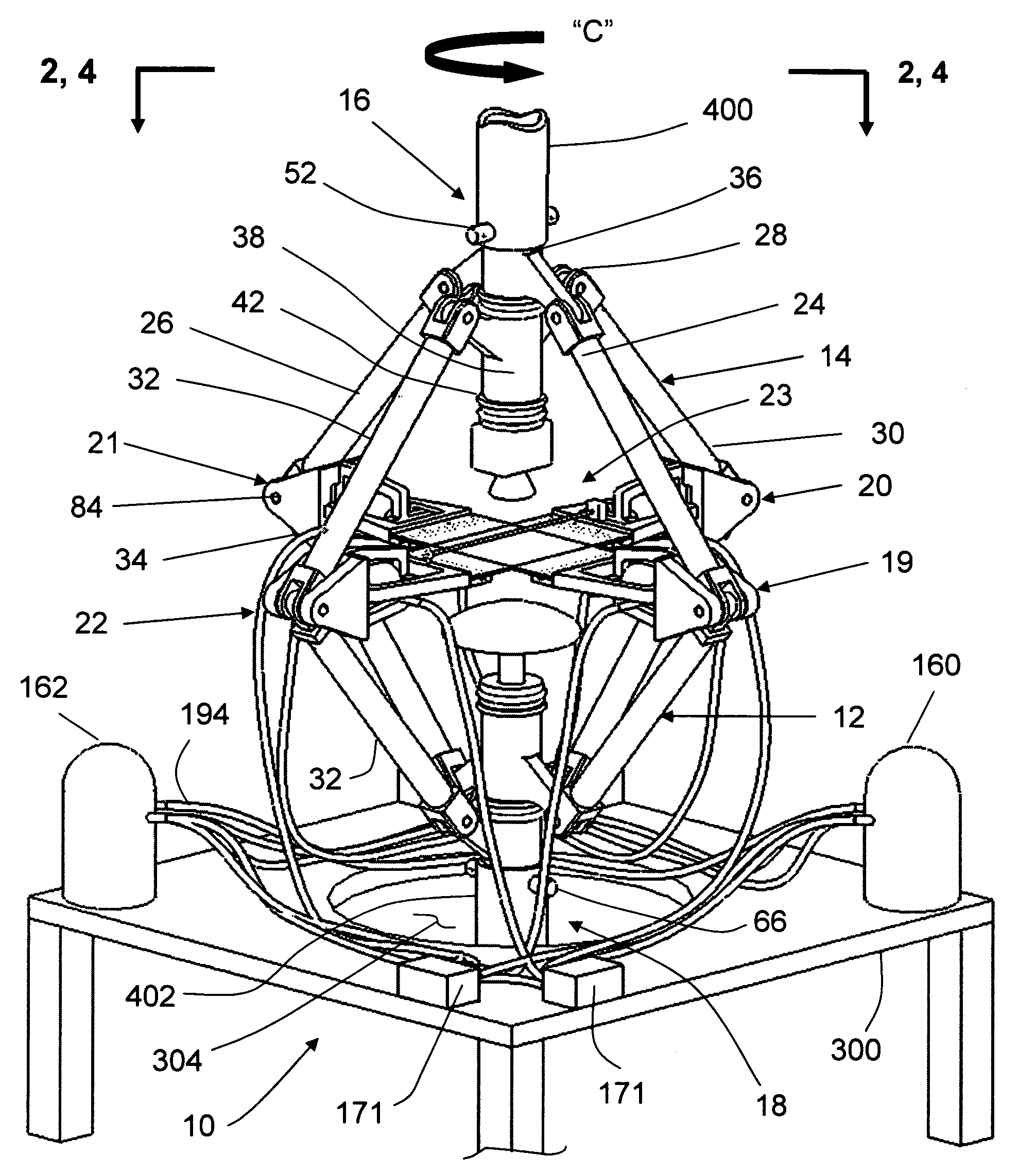
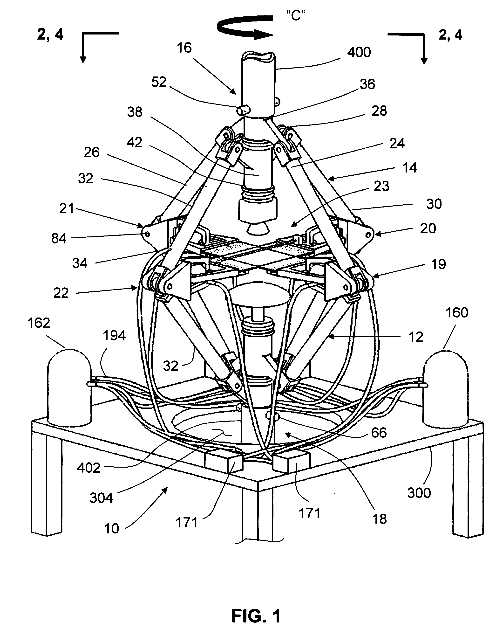
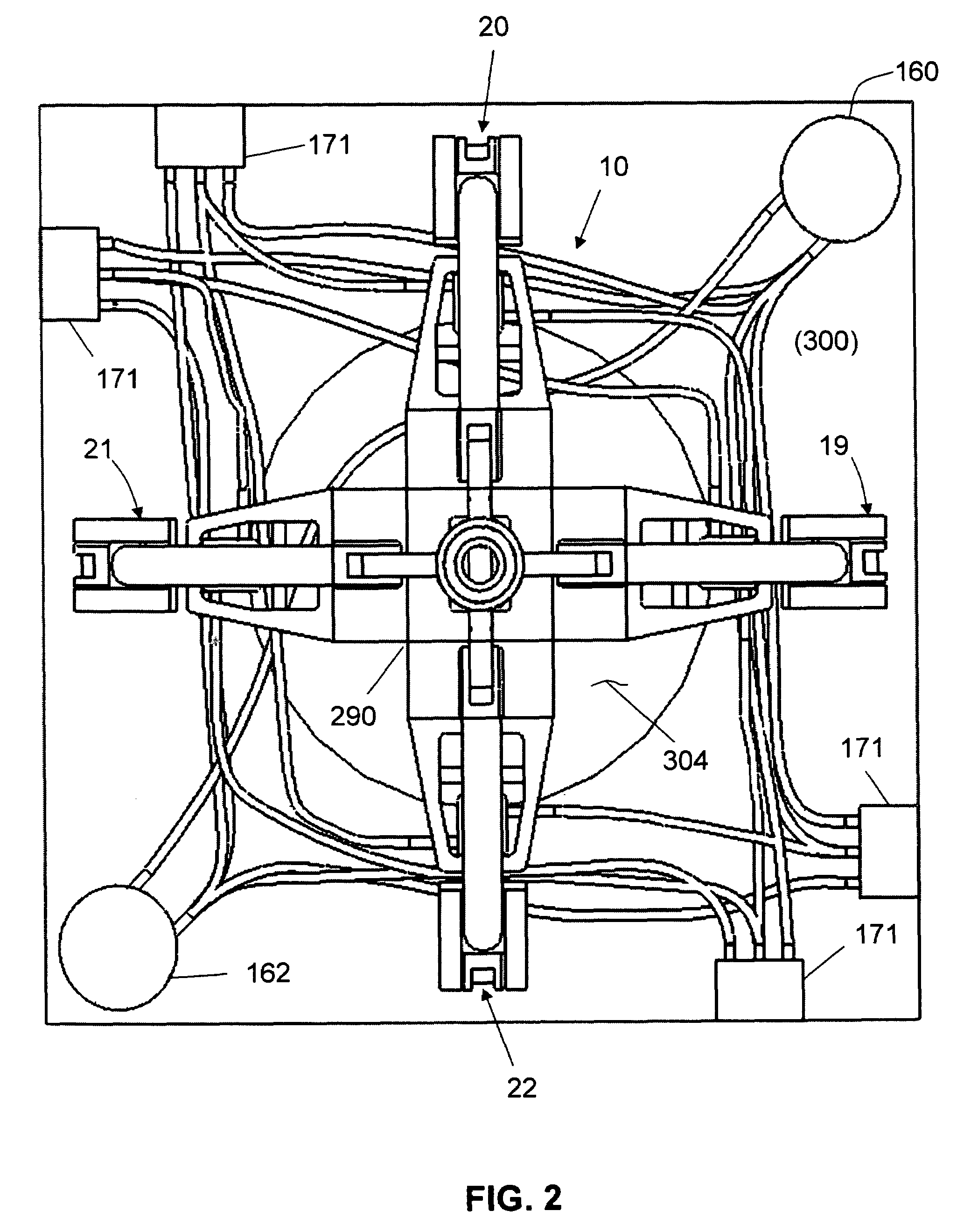
FIGS. 1–5 depict an embodiment of the biaxial testing apparatus 10 (hereinafter known as the apparatus) of the present invention.

[0050]The apparatus 10 generally comprises two rhombus-shaped four-bar linkages 12 and 14, a superior (top) joint 16, an inferior (bottom) joint 18, loading plate assemblies 19, 20, 21, 22 and a strain / displacement measurement system 23.

[0051]The linkage 12 includes two pairs of link bars 24 and 26, extending from the superior joint 16 to the inferior joint 18. Ends of each link bar are rigidly connected to brackets 28 that pivotally connect to the superior joint 16 and the inferior joint 18. Similarly, the linkage 14 includes two pairs of link bars 30 and 32, extending from the superior joint 16 to the inferior joint 18. The ends of each link bar are rigidly connected to the brackets 28 that pivotally connect to the superior joint 16...


PUM


Abstract

A testing apparatus having four-bar linkages pivotable to sleeves on opposite vertices with the sleeves of each vertex rotationally attached to each other. Links of each linkage are pivotally attached to loading plate assemblies securing a test specimen. During loading, the assemblies move toward or away from each other; thereby, applying compression or tension to the specimen. A pressure system fluidly impacts opposite faces of a piston of the assembly such that one of the faces is pressurized and impacts arms of the assembly for a sliding motion to move toward or away from the longitudinal axis of the apparatus thereby, applying a compression or tensile load on the specimen or augmenting the loads applied by the movement of the loading plate assemblies. The pressure system includes a controller connected to a reservoir, a pressurized source, a plurality of shutoff valves and pressure-adjustable check valves.

Description

CROSS-REFERENCE TO RELATED APPLICATIONS[0001]This application is a continuation-in-part of and claims the benefit of U.S. patent application Ser. No. 10 / 905,076—filed on Dec. 14, 2004 now U.S. Pat. No. 7,051,600 and allowed on Dec. 30, 2005, entitled “Triaxial Tension Compression, Shear Testing Apparatus” which is a continuation-in-part of and claims the benefit of U.S. patent application Ser. No. 10 / 851,748—filed on May 24, 2004 and issued on Mar. 1, 2005 as U.S. Pat. No. 6,860,156, entitled “Combined In-Plane Shear and Multi-Axial Tension or Compression Testing”.STATEMENT OF GOVERNMENT INTEREST[0002]The invention described herein may be manufactured and used by or for the Government of the United States of America for governmental purposes without the payment of any royalties thereon or therefor.BACKGROUND OF INVENTION[0003](1) Field of the Invention[0004]The present invention relates to a combined in-plane shear and biaxial tension or compression loading apparatus, having hydraul...

Claims


Application Information

Patent Timeline
IPC IPC(8): G01D7/00
CPCG01N3/10G01N2203/0017G01N2203/0025G01N2203/0254G01N2203/027G01N2203/0278G01N2203/0282G01N2203/0411
Inventor SADEGH, ALI M.CAVALLARO, PAUL V.QUIGLEY, CLAUDIA J.
Owner NAVY UNITED STATES OF AMERICA
Why Eureka
Try Eureka