Method of operating an internal combustion engine with direct fuel injection

a technology of internal combustion engine and fuel injection, which is applied in the direction of combustion engines, machines/engines, electric control, etc., can solve the problems of reducing the moment generated during combustion, reducing the quantity of injected fuel, and limited exhaust gas recirculation rate, so as to improve combustion stability, reduce nitrogen oxide emissions, and increase the effect of turbulen

Active Publication Date: 2007-04-17
DAIMLER AG
View PDF7 Cites 19 Cited by
  • Summary
  • Abstract
  • Description
  • Claims
  • Application Information

AI Technical Summary

Benefits of technology

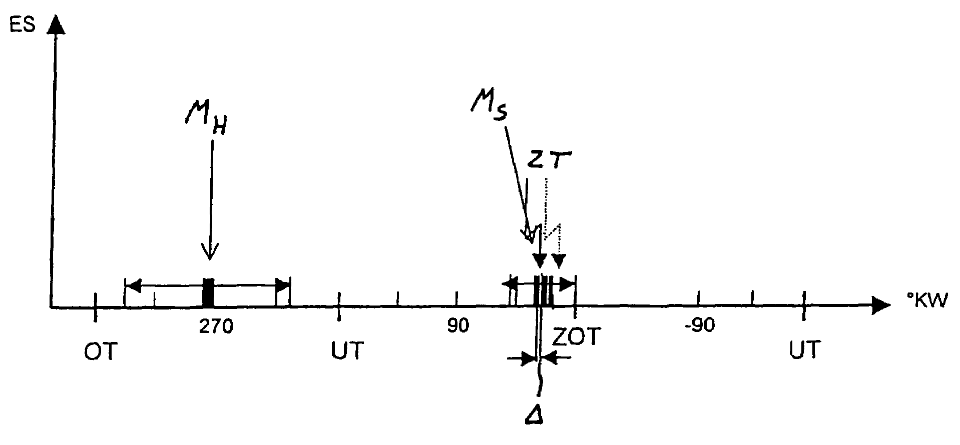
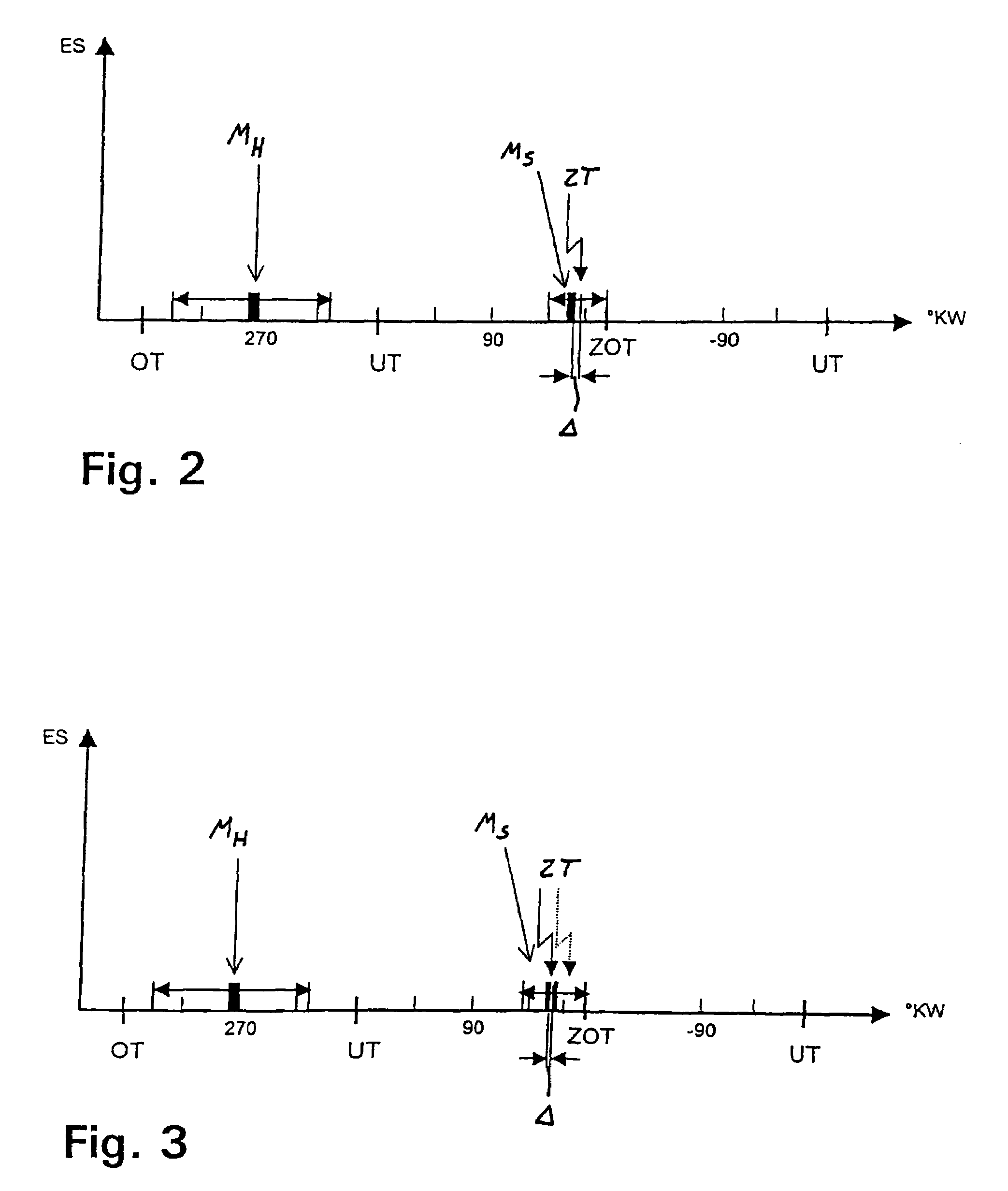
[0009]In the method according to the invention, the fuel quantity which is injected into the combustion chamber is divided into two injection quantities. The pilot injection takes place during the intake stroke of the internal combustion engine in order to form a homogeneous, lean air / fuel mixture in the entire combustion chamber. The main injection into the combustion chamber during the compression stroke of the internal combustion engine forms a stratified, rich air / fuel mixture charge cloud in the region of the spark plug directly before the ignition time, so that reliable combustion of said charge cloud is permitted even at very late ignition times. In addition, the stratified main injection generates intensified turbulence at high pressure in the region of the spark plug. The homogeneous, lean pilot injection provides a relatively high excess of air, which brings about a reduction in nitrogen oxide emissions, and the stratified, rich main injection improves the combustion stability in order to ensure the same degree of running smoothness of the internal combustion engine. This optimizes the advantage of the fuel saving obtained by operating the internal combustion engine at high residual exhaust gas rates or with very lean charge mixtures.
[0010]In a preferred embodiment of the invention, the main injection is carried out as a multiple injection with a plurality of stratified injections in rapid succession. Said multiple injection improves the mixture of the fuel, which is injected in a stratified fashion, with the fresh air and the residual exhaust gas, increases the degree of turbulence in the region of the spark plug and therefore further stabilizes the combustion.
[0017]In a further preferred embodiment of the invention, the pilot injection is also carried out as a multiple injection with a plurality of homogeneous injections. This measure further improves the homogeneity of the air / fuel mixture in the entire combustion chamber.

Problems solved by technology

However, the possible exhaust gas recirculation rate is limited by the combustion stability deteriorating with an increasing exhaust gas content in the combustion gas.
The inert gas is heated by the hot combustion gas during combustion and correspondingly deprives the combustion gas of energy.
The moment generated during combustion is predefined by the injected fuel quantity reduced by the relatively low combustion efficiency of lean combustion.
Those nitrogen oxides cannot be reduced to nitrogen and oxygen by a 3-way catalytic converter as a result of the presence of oxygen in the combustion gas, and must be eliminated by means of a NOx storage catalytic converter or similar expensive exhaust gas purification techniques.

Method used


Image

  • Method of operating an internal combustion engine with direct fuel injection
  • Method of operating an internal combustion engine with direct fuel injection
  • Method of operating an internal combustion engine with direct fuel injection

Examples


Embodiment Construction

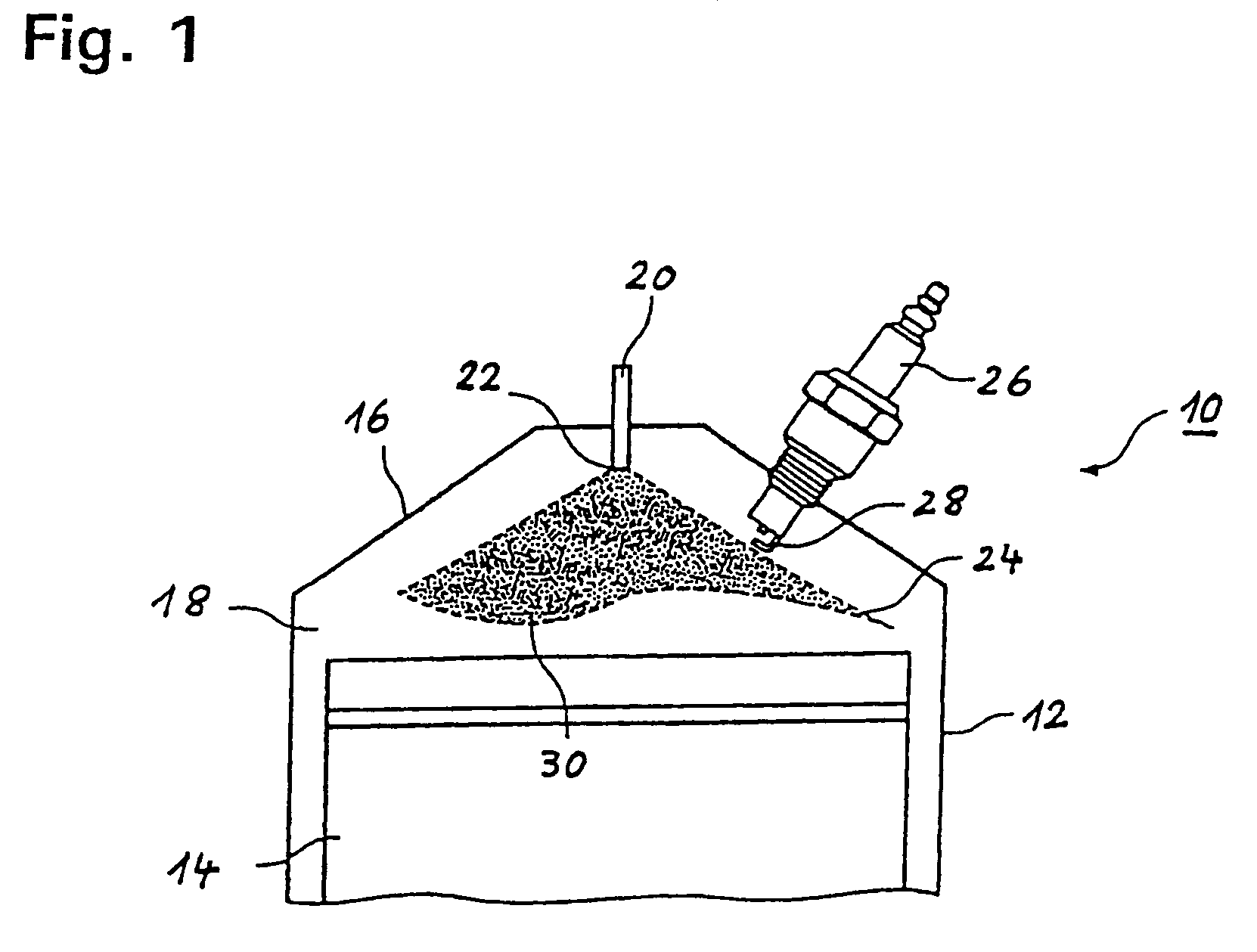
[0024]FIG. 1 shows in a considerably simplified view a cylinder 12 of a spark ignition internal combustion engine 10 with direct fuel injection. In the cylinder 12, a combustion chamber 18 is delimited by a piston 14 and a cylinder head 16 which closes off the cylinder 12. A fuel injector 20, which can inject fuel into the combustion chamber 18 through a nozzle opening 22, is arranged centrally in the cylinder head 16. During a start phase of the internal combustion engine 10, a control device (not illustrated) determines, inter alia, the injection times of the fuel, with the associated fuel quantities, and an ignition time point at which an air / fuel mixture, which is formed in the combustion chamber, is ignited by means of a spark plug 26 or the like.

[0025]When the nozzle opening 22 of the fuel injector 20 is unblocked, the fuel is injected into the combustion chamber 18 in the form of a conical jet 24 with an opening angle of between 70° and 110°. The spark plug 26 is positioned i...


PUM


Abstract

In a method of operating a spark ignition internal combustion engine with direct fuel injection wherein combustion air is supplied to a combustion chamber, fuel is injected into the combustion air during an intake stroke via a fuel injector in a pilot injection using a first fuel quantity so as to from a homogeneous lean air / fuel mixture in substantially the entire combustion chamber, in a main injection subsequently a second fuel quantity is injected in multiple injection steps just before ignition time so as to form a stratified rich air / fuel mixture in the area of a spark plug and the stratified fuel charge is then ignited 2° CA to 10° CA after completion of the injection of the main stratified injection.

Description

[0001]This is a continuation-in-part application of pending international application PCT / EP2005 / 003414 filed Apr. 1, 2005 and claiming the priority of German patent application 10 2004 017 989.1 filed Apr. 14, 2004.BACKGROUND OF THE INVENTION[0002]The invention relates to a method of operating a spark-ignition internal combustion engine, in particular a spark-ignition internal combustion engine with direct fuel injection wherein, in an initial fuel injection event, fuel is injected into the intake air to form in a cylinder a lean charge mixture and, in a main fuel injection event, a stratified rich mixture is established in the vicinity of the spark plug and is ignited by the spark plug.[0003]In gasoline engines with intake pipe injection and in direct-injection gasoline engines operated in a homogeneous operating mode, a reduction in fuel consumption can be obtained by means of internal residual exhaust gas retention or external recirculation of combustion gases. Said reduction is...

Claims


Application Information

Patent Timeline
Patent Type & Authority Patents(United States)
IPC IPC(8): F02B3/10F02B17/00F02D41/00F02D41/30F02D41/40
CPCF02D41/3023F02D41/402F02D41/0057F02D41/405Y02T10/44Y02T10/40
Inventor OECHSLE, MICHAELLUX, CHRISTOPF
Owner DAIMLER AG
Why Eureka
Try Eureka