Unlock instant, AI-driven research and patent intelligence for your innovation.
Construction machine
Inactive Publication Date: 2007-04-17
KOMATSU LTD +1
View PDF8 Cites 16 Cited by
Summary
Abstract
Description
Claims
Application Information
AI Technical Summary
This helps you quickly interpret patents by identifying the three key elements:
Problems solved by technology
Method used
Benefits of technology
Benefits of technology
[0022]The present invention has been designed in consideration of this situation, and it is an object thereof to provide a construction machine in which a load that is transmitted during an operation is transferred to a location having good rigidity, thereby securing the strength of a vehicle body, and which is also capable of realizing an increase in the load-withstanding strength in relation to a load that is applied during travel, thereby improving reliability.
Problems solved by technology
In this case, the side plate of the rotary case portion is provided at a remove from the location of the upper plate of the rotary case portion on which the slewing body is mounted, and as a result, loads transmitted from the slewing body are transferred to the upper plate having low load-withstanding strength, leading to possible breakage of the rotary case portion depending on the structure thereof.
Method used
Image
Click on the blue label to locate the original text in one second.
Reading with bidirectional positioning of images and text.
Examples
first embodiment
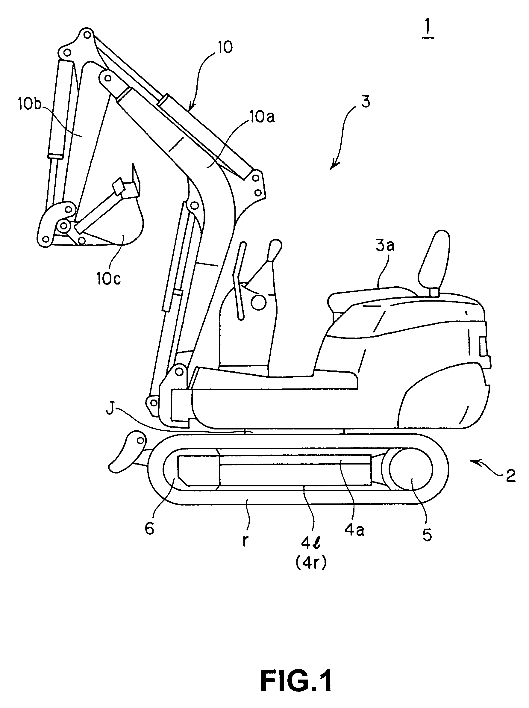
[0049]As shown in FIG. 1, a hydraulic shovel 1 according to the present invention comprises a lower traveling body 2 provided with a crawler belt r to enable motion, and an upper slewing body 3 which is attached slewably to the top of the lower traveling body 2 via a slewing bearing J, and which is mounted by an operator to perform an operation.
[0050]An operating seat 3a on which the operator sits to perform an operation is provided on the upper slewing body 3, and a working machine 10 comprising a boom 10a, an arm 10b, and an excavating bucket 10c attached to the tip end of the arm 10b, which are hydraulically driven, is axially supported in a vertical direction to the front of the operating seat 3a so as to swing freely.
[0051]As a result of this constitution, various loads act on the upper slewing body 3, to which the working device 10 comprising the bucket 10c is attached, during an operation.
[0052]In the lower traveling body 2, a drive shaft 5 and a pivot 6 are attached respecti...
second embodiment
[0121]Next, a second embodiment will be described.
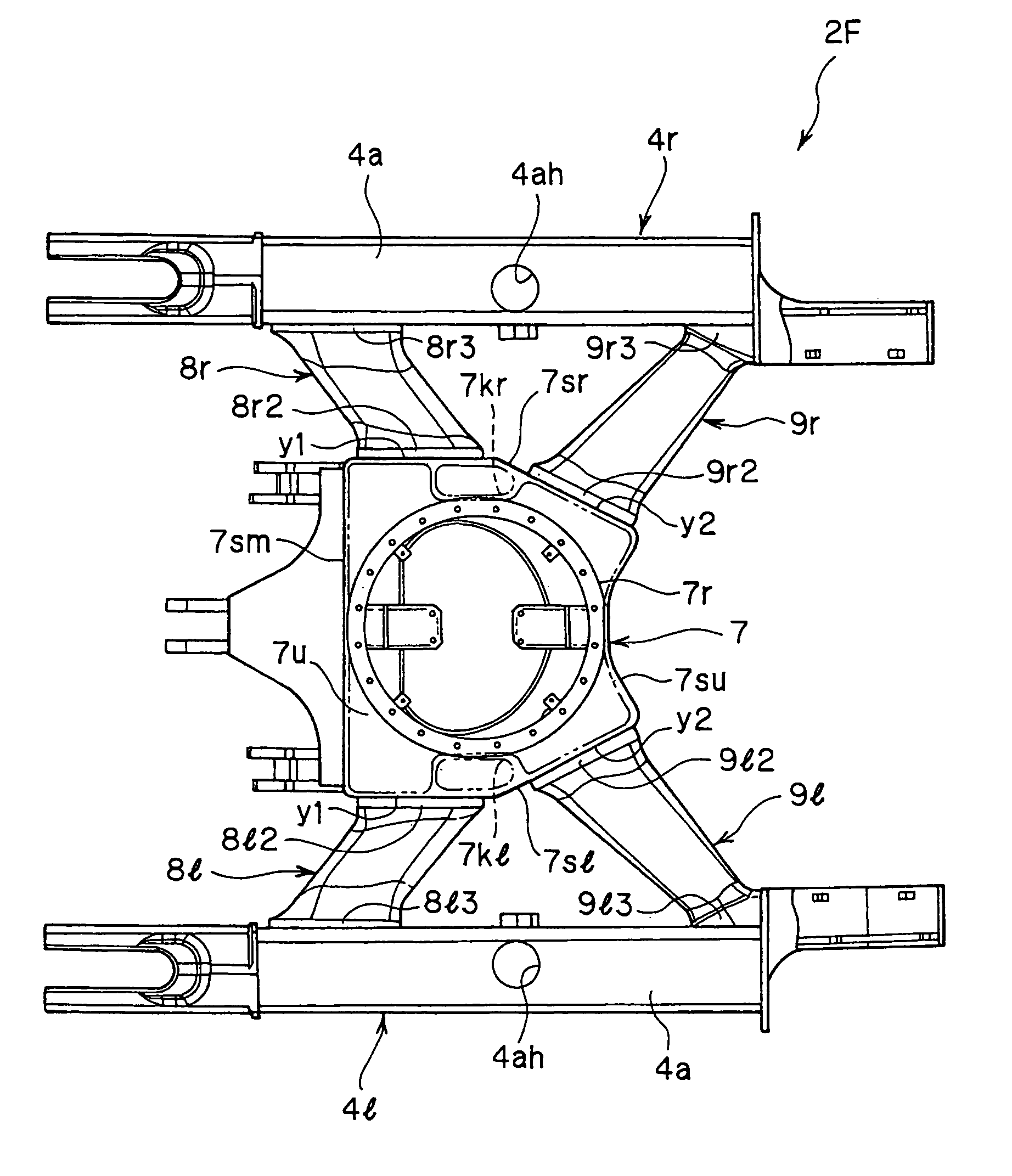
[0122]In the second embodiment, the reinforcing ribs 7kr, 7kl of the first embodiment are not provided below the attachment ring 7r in the interior of the center frame 7, but are substituted for the right side plate 7sr and left side plate 7sl.
[0123]All other constitutions are identical to those of the first embodiment. Hence identical constitutional elements to those of the first embodiment are illustrated by adding to the same reference symbol, and detailed description of these elements is omitted.
[0124]As shown in the top view in FIG. 7, a center frame 27 is disposed in the central portion of a frame 21F of the lower traveling body, and truck frames 4r′, 4l′ are disposed on the two side portions thereof. The truck frame 4r′ is connected to the center frame 27 by two leg-shaped connecting members 8r′, 9r′, and the truck frame 4l′ is connected to the center frame 27 by two leg-shaped connecting members 8l′, 9l′.
[0125]These members...
PUM
Abstract
A construction machine where an operating load is transferred to a location having good rigidity, thereby ensuring the strength of a vehicle body and increasing the load-withstanding strength in relation to running loads. The frame of the lower traveling body of the construction machine comprising a hollow center frame having an upper plate with an attachment ring, a lower plate, and side plates that surrounding sides of the frame and that jut out from the attachment ring, and reinforcing ribs which connect the upper plate to the lower plate in the interior of the center frame beneath the attachment ring.
Description
BACKGROUND OF THE INVENTION[0001]1. Field of the Invention[0002]The present invention relates to a construction machine such as a hydraulic shovel, and more particularly to a frame constitution of a lower traveling body in a construction machine.[0003]2. Description of the Related Art[0004]A conventional hydraulic shovel 100 disclosed in “Crawler-type Vehicle” (Japanese Unexamined Patent Application Publication 2002-178960) comprises a traveling body 101 to enable movement, and a slewing body 102 which is mounted slewably above the traveling body 101, as shown in FIG. 9.[0005]The slewing body 102 comprises a slewing frame 103, and the stewing frame 103 is provided with a body cover 104 accommodating a motor and the like, a cab 105 which defines the operating cabin, a counterweight 106, and so on, for example.[0006]A working device 107 is provided elevatably at the front portion of the slewing body 102.[0007]A truck frame 108 constituting the main body part of the traveling body 101 ...
Claims
Application Information
Patent Timeline
Application Date:The date an application was filed.
Publication Date:The date a patent or application was officially published.
First Publication Date:The earliest publication date of a patent with the same application number.
Issue Date:Publication date of the patent grant document.
PCT Entry Date:The Entry date of PCT National Phase.
Estimated Expiry Date:The statutory expiry date of a patent right according to the Patent Law, and it is the longest term of protection that the patent right can achieve without the termination of the patent right due to other reasons(Term extension factor has been taken into account ).
Invalid Date:Actual expiry date is based on effective date or publication date of legal transaction data of invalid patent.

