
Bicycle lighting device

a technology of lighting device and bicycle, which is applied in the direction of bicycle equipment, lighting and heating apparatus, optical signal, etc., can solve the problems of inability to illuminate led, loss at low speed due to resistor, and maybe destruction of led, so as to achieve effective illumination of light emitting diodes at low speed ranges, increase forward voltage, and bright light

Inactive Publication Date: 2007-04-17
SHIMANO INC
View PDF23 Cites 4 Cited by
  • Summary
  • Abstract
  • Description
  • Claims
  • Application Information

AI Technical Summary

Benefits of technology

The present invention is a bicycle lighting device that uses a generator to drive LED lights. However, the generator output may vary depending on the bicycle speed, which can cause the LED to be destroyed or not illuminate. To solve this problem, a protector circuit is used to control the voltage and current flow to the LED. The protector circuit includes resistors and Zener diodes to limit the current flow and avoid excessive heat. The resistance value of the resistors needs to be increased to handle high speeds, but this can cause loss of brightness at low speeds. To address this, a linear voltage regulator method using transistors can be used, but this method also has significant circuit loss. The invention proposes a new method using a protector circuit that restricts the flow of electric current to each LED, allowing for efficient illumination at low speeds. The invention also suggests using multiple light emitting diodes connected in series or parallel to control the current flow and brightness. A rectifier circuit can also be added to improve efficiency. Overall, the invention provides a way to protect the LED without a special protector circuit and effectively illuminate at low speeds.

Problems solved by technology

When generator output is used to drive the LED, the generator output varies according to the bicycle speed as outlined above, and the LED either may not illuminate, or the LED maybe destroyed by the flow of excessive current.
However, if the resistor resistance value is too large, the loss at low speeds due to the resistor becomes significant, and it becomes impossible to illuminate the LED at these low speeds.
However, when this sort of circuit is used, there is a significant voltage drop (circuit loss) in the circuit, and it becomes impossible to drive the LED at low speeds, as described above.

Method used


Image

  • Bicycle lighting device
  • Bicycle lighting device
  • Bicycle lighting device

Examples


Embodiment Construction

[0034]Selected embodiments of the present invention will now be explained with reference to the drawings. It will be apparent to those skilled in the art from this disclosure that the following descriptions of the embodiments of the present invention are provided for illustration only and not for the purpose of limiting the invention as defined by the appended claims and their equivalents.

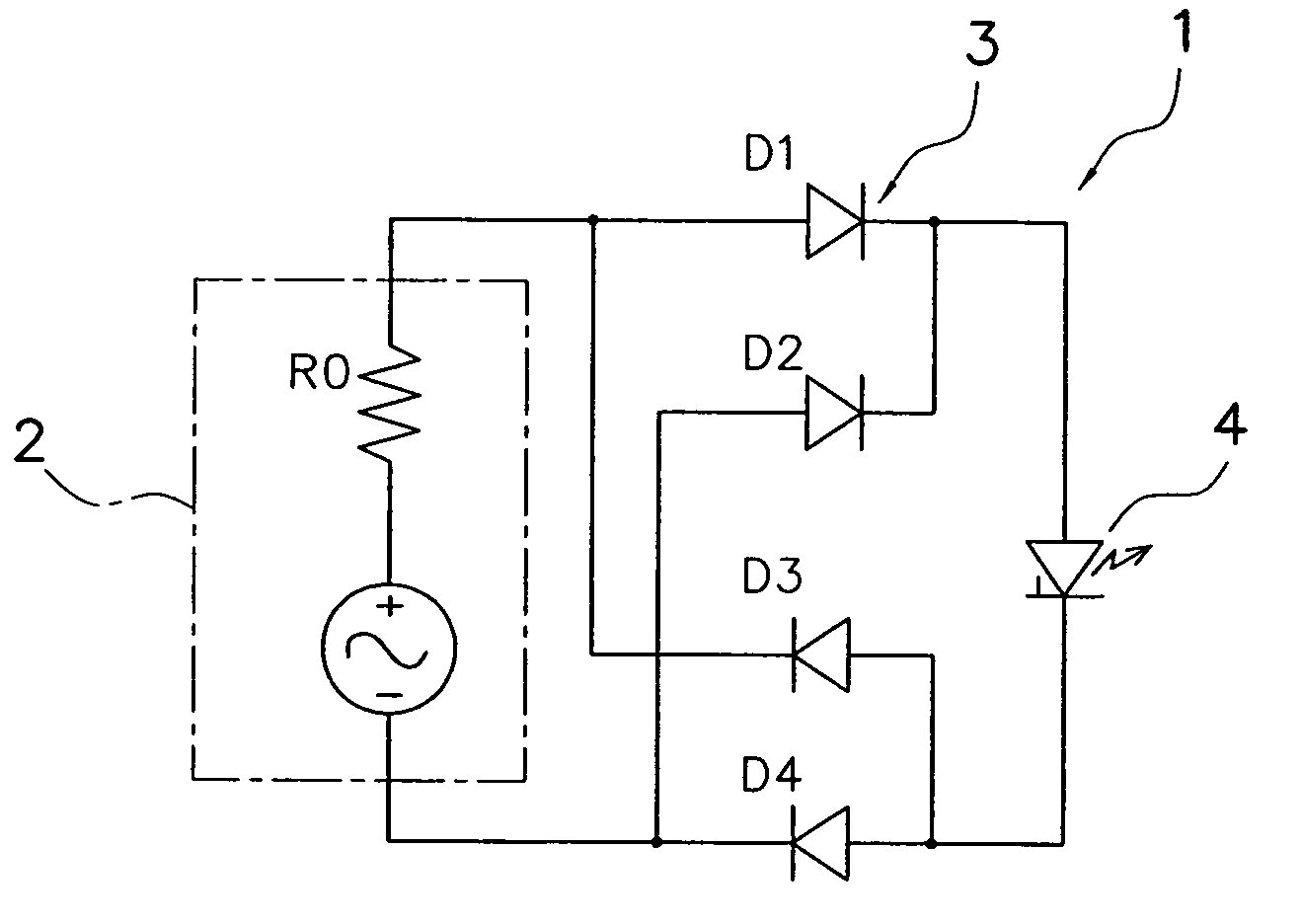
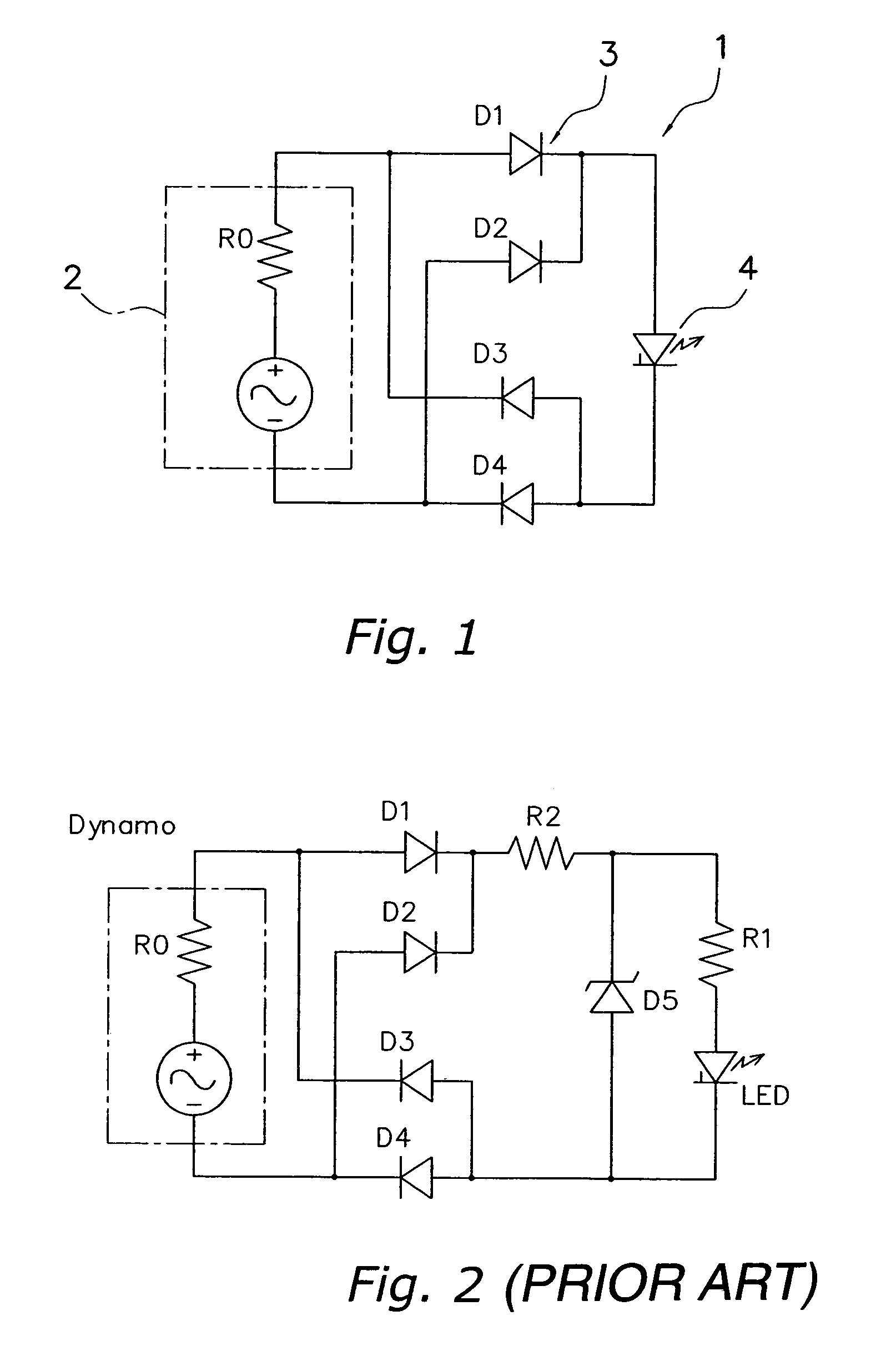
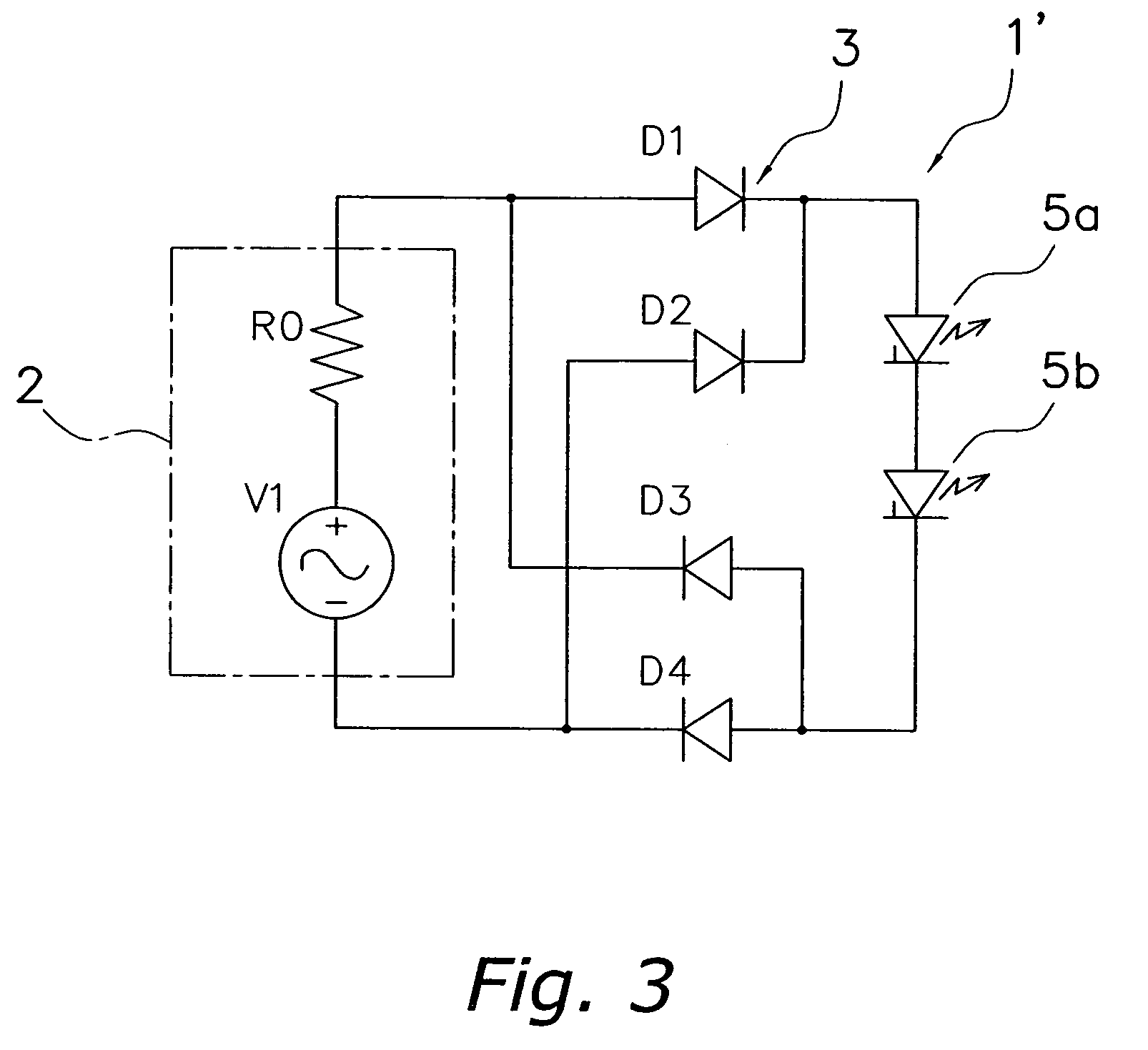
[0035]Referring initially to FIG. 1, a bicycle lighting device 1 is illustrated in accordance with a first embodiment of the present invention. This lighting device 1 is used as a bicycle headlight L (see FIG. 10), and is connected to a generator 2 provided in the bicycle hub G (see FIG. 10). The lighting device 1 has a full wave rectifier 3, a generator 2 on the output side of the full wave rectifier 3, and an LED 4 connected in series to the light emitting diode unit. The full wave rectifier 3 is a bridge rectifier circuit comprising four connected diodes, D1, D2, D3, and D4.

[0036]FIG. 2 shows a ...


PUM


Abstract

A bicycle lighting device is configured to make possible the efficient illumination of an LED while controlling power loss between the generator and the LED. An LED unit has at least one LED. A protector circuit controls the flow of current to each LED according to the internal resistance of the generator and the constant voltage properties of the LED unit.

Description

[0001]This application claims priority to Japanese Patent Application No. 2004-009192. The entire disclosure of Japanese Patent Application No. 2004-009192 is hereby incorporated herein by reference.BACKGROUND OF THE INVENTION[0002]1. Field of the Invention[0003]This invention generally relates to bicycle lighting devices. More specifically, the present invention relates to bicycle lighting devices that are illuminated by a bicycle generator.[0004]2. Background Information[0005]Bicycle lighting devices, particularly headlights, have been proposed as in the device indicated in Japanese Laid Open Patent Publication No. 2003-291870. This device comprises a light emitting diode (LED) housed within a headlight, a light bulb, and a power source for illuminating or flashing the LED. The power source is a secondary battery which is charged by a solar cell.[0006]Further, bicycles using generators to illuminate bicycle headlights have already been proposed (for example, Japanese Laid Open Pat...

Claims


Application Information

Patent Timeline
Patent Type & Authority Patents(United States)
IPC IPC(8): B62J6/00B62J6/02H05B37/00H05B44/00
CPCB62J6/001H05B33/0809H05B33/0803Y02B20/341B62J6/01Y02B20/30H05B45/30
Inventor UNO, KOJI
Owner SHIMANO INC
Learn More