Controller for machine effecting end

a technology of controlling end and machine, which is applied in the direction of electric programme control, program control, instruments, etc., can solve the problems of inability to neglect, the motion of the driven element with respect to the machine effecting end does not always agree with the command motion, and the driven element is liable to vibra

Active Publication Date: 2007-04-17
FANUC LTD
View PDF9 Cites 22 Cited by
  • Summary
  • Abstract
  • Description
  • Claims
  • Application Information

AI Technical Summary

Benefits of technology

[0015]Thus, an amount of positional displacement of the machine effecting end to which a tool is attached is detected, and the position of the machine effecting end, inclusive of the displacement, is controlled by the learning control so as to coincide with the commanded position. Consequently, even in the case where the machine rigidity is low and thus positional displacement between the driven element driven by the motor and the machine effecting end is caused due to strain or torsion, such displacement can be corrected, enabling the machine effecting end to move as commanded. Also, where a machine tool is required to perform high-speed, high-precision machining and thus even slight positional displacement between the driven element driven by a motor and the machine effecting end attributable to strain or torsion should not be overlooked, it is possible to carry out high-speed, high-precision machining satisfactorily.

Problems solved by technology

Even while such position, velocity and current feedback controls are performed, the driven element is liable to vibrate when the acceleration of the servomotor suddenly changes.
Specifically, when the driven element vibrates, the vibration component contained in the acceleration signal indicative of the acceleration of the driven element detected by the acceleration sensor constitutes an error with respect to the current command for the current feedback control.
However, in the case of a machine tool of which the rigidity between the driven element and the machine effecting end is low, the motion of the driven element with respect to the machine effecting end do not always agree with commanded motion.
Further, in cases where a machine tool which is required to perform high-speed, high-precision machining is operated at high acceleration, positional displacement between the driven element and the machine effecting end caused due to torsion or the like occasionally becomes so large that it cannot be neglected, even if the machine rigidity is relatively high.

Method used


Image

  • Controller for machine effecting end
  • Controller for machine effecting end
  • Controller for machine effecting end

Examples


first embodiment

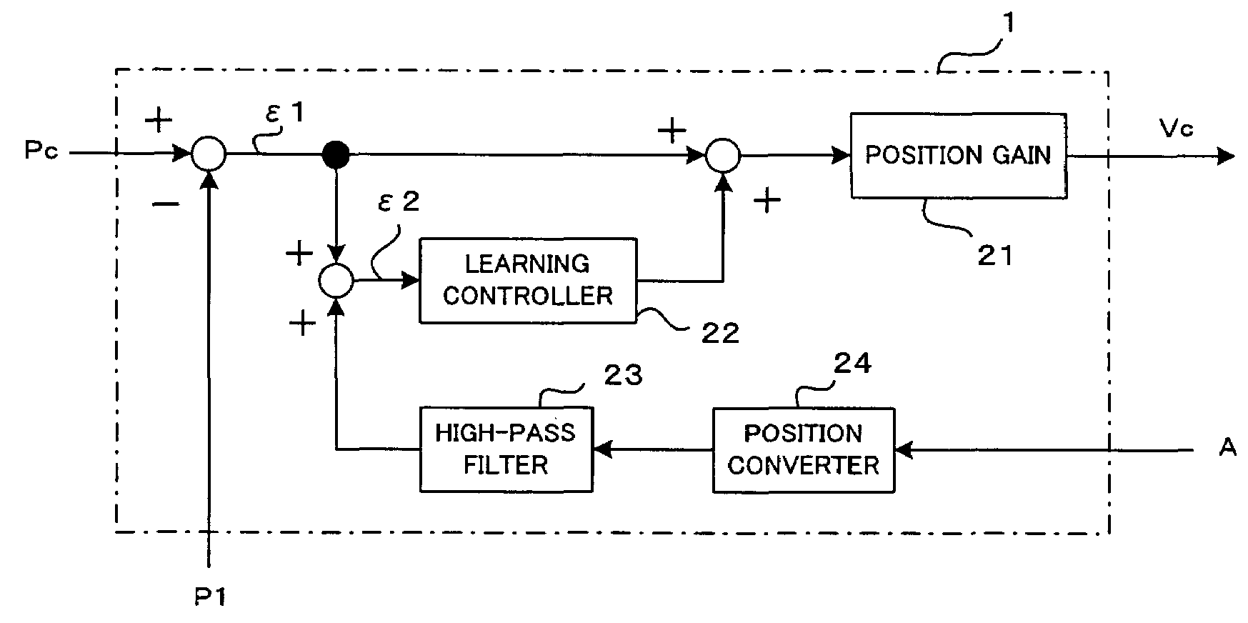
[0034] in each position loop control interval, the second position deviation ε2 is added to the correction value x stored in the immediately preceding position loop interval of the pattern repeated at predetermined intervals, and the sum obtained is filtered through the band-limiting filter 22a for stabilizing the controlled system and then stored in the delay element memory 22b as the correction value x of the present position loop control interval. Also, the correction value x of the immediately preceding position loop interval of the repeated pattern, stored in the delay element memory 22b, is compensated for a phase lag and gain drop of the controlled system by the dynamic characteristic compensation element 22c, and the result is output from the learning controller 22. In the position control section 1, the first position deviation ε1 and the output of the learning controller 22 are added together, and the sum obtained is multiplied by the position gain 21, the result being out...

second embodiment

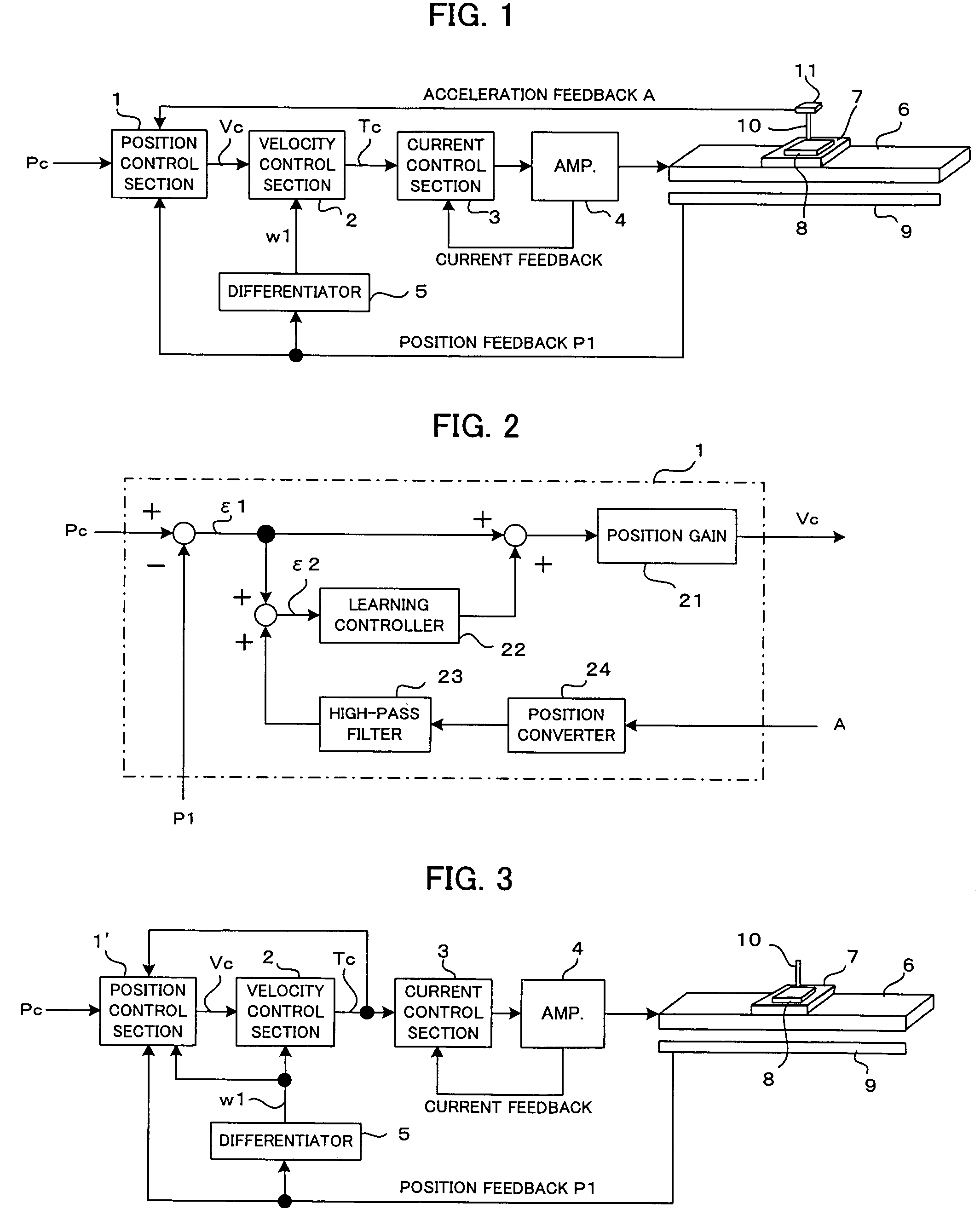
[0036]FIG. 3 is a block diagram showing a principal part of the present invention.

[0037]In the second embodiment, the acceleration sensor is not used. Instead, the position of the machine effecting end is predicted by using a machine model and is controlled so as to coincide with the commanded position. First, the principle of operation of the second embodiment will be explained.

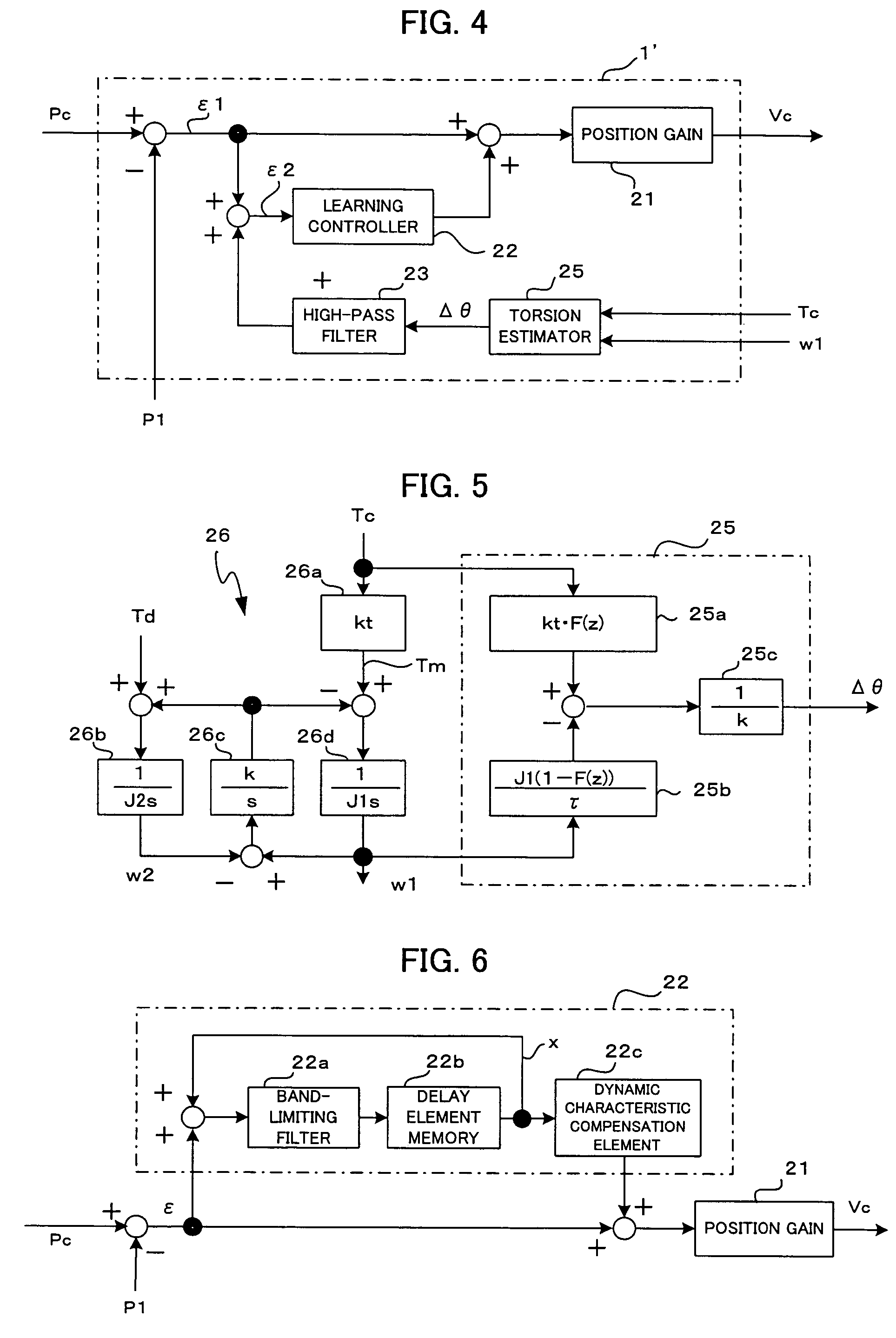
[0038]Where the relationship of the position detector and the machine effecting end is represented as a two-inertia system with the friction term neglected, the following equations (1) and (2) hold with respect to the motor side and the machine side, respectively:

[0039]J⁢⁢1·w⁢⁢1·s=Tm-k⁡(w⁢⁢1-w⁢⁢2)s(1)J⁢⁢2·w⁢⁢2·s=k⁡(w⁢⁢1-w⁢⁢2)s+Td(2)

[0040]In the above equations (1) and (2), J1 is the motor inertia, J2 is the machine inertia, w1 is the motor velocity, w2 is the velocity of the machine effecting end, k is the spring constant of the machine, Tm is the commanded torque, Td is the disturbance torque, and s is the ...


PUM


Abstract

A controller for controlling a position of a driven element with respect to a machine effecting end so as to be in accord with a command. An acceleration sensor is mounted to a member of the machine effecting end to which a tool is attached. Acceleration detected by the sensor is subjected to second-order integration by a torsion estimator to obtain displacement Δθ of the machine effecting end from the original position. Position feedback P1 of a driven element is subtracted from position command Pc to obtain first position deviation ε1. The displacement Δθ is added to the first position deviation ε1 to obtain second position deviation ε2. The second position deviation ε2 is subjected to learning control of a learning controller to obtain a correction value, which is added to the first position deviation ε1 to obtain velocity command Vc. The second position deviation is the sum of the displacement ε1 of the driven element from the commanded position and the displacement Δθ of the machine effecting end relative to the driven element, and thus signifies a positional displacement of the machine effecting end from the commanded position. The second position deviation is subjected to the learning control so as to converge to “0”, whereby the position of the driven element with respect to the machine effecting end becomes in accord with the command.

Description

BACKGROUND OF THE INVENTION[0001]1. Field of the Invention[0002]The present invention relates to a controller for controlling a machine tool, and more particularly to a position control of a driven element with respect to a machine effecting end in the machine tool.[0003]2. Description of Related Art[0004]In machine tools, to control the position and velocity of a driven element driven by a servomotor, position feedback control and velocity feedback control as well as current feedback control are usually performed so that the position and velocity of the driven element may be in accord with the commanded position and velocity.[0005]Even while such position, velocity and current feedback controls are performed, the driven element is liable to vibrate when the acceleration of the servomotor suddenly changes. To avoid this, a control method has been proposed wherein an acceleration sensor for detecting the acceleration of a driven element is provided, a signal output from the accelerat...

Claims


Application Information

Patent Timeline
Patent Type & Authority Patents(United States)
IPC IPC(8): G05B19/416
CPCG05B19/404
Inventor IWASHITA, YASUSUKETOYOZAWA, YUKIOSONODA, NAOTO
Owner FANUC LTD
Why Eureka
Try Eureka