Control device with learning function for electric motors

a technology of electric motors and control devices, applied in the direction of program control, dynamo-electric converter control, instruments, etc., can solve the problems of difficult to precisely move the workpiece, the workpiece may be bent or twisted, and the inability to realize the precise rotational control of the workpi

Active Publication Date: 2009-04-23
FANUC LTD
View PDF10 Cites 14 Cited by
  • Summary
  • Abstract
  • Description
  • Claims
  • Application Information

AI Technical Summary

Benefits of technology

[0015]The control device of the invention may further comprise a gain adjusting part for automatically adjusting a speed gain of one of the electric motors so that the difference between each amount of correction of positional deviation output by each learning part is minimized.

Problems solved by technology

In a machine such as a machine tool or an industrial machine, in the case that an object or a workpiece, having relatively low stiffness, such as a thin pin or a thin plate needs be moved, if a force for moving the workpiece is applied to a part of the workpiece which is far from the center of gravity of the workpiece, the workpiece may be bent or twisted, whereby it may be difficult to precisely move the workpiece.
For example, when a cantilever-type workpiece having low stiffness is rotated and processed, the workpiece may be twisted due to acceleration or deceleration of torque and / or a machining load, whereby a precise rotational control of the workpiece cannot be realized.
However, depending on the configuration of the machine and / or the type of the workpiece, an imbalance may occur between each load applied to each electric motor.
For example, in the case that the workpiece is rotated while both ends thereof are held, when a load applied to one electric motor becomes larger than a load applied to another electric motor, the response of the first electric motor is lowered and a delay occurs in acceleration / deceleration of the electric motor, whereby the workpiece may be twisted or vibrated.
However, since there are a variety of workpieces such adjustment requires many man-hours.
In such a case, the response of each electric motor may be different, whereby precise control cannot be realized.
However, if the stiffness of the workpiece is relatively low, the workpiece may be easily bent or twisted.
Therefore, if the amount of correction obtained by the learning control is used for controlling the other electric motors, precise control is not always possible.
Further, when there is an imbalance between each load of each electric motor, even if the learning control as described in Japanese Unexamined Patent Publication No. 11-305839 is used, it is difficult to execute precise control because the response of each electric motor is different from each other.
In addition, the technique as described in Japanese Unexamined Patent Publication No. 2007-42068 is intended to reduce a synchronous error between a master side and a slave side, and therefore the technique cannot solve the above problem based on the difference between each response of the electric motors.

Method used


Image

  • Control device with learning function for electric motors
  • Control device with learning function for electric motors
  • Control device with learning function for electric motors

Examples


Embodiment Construction

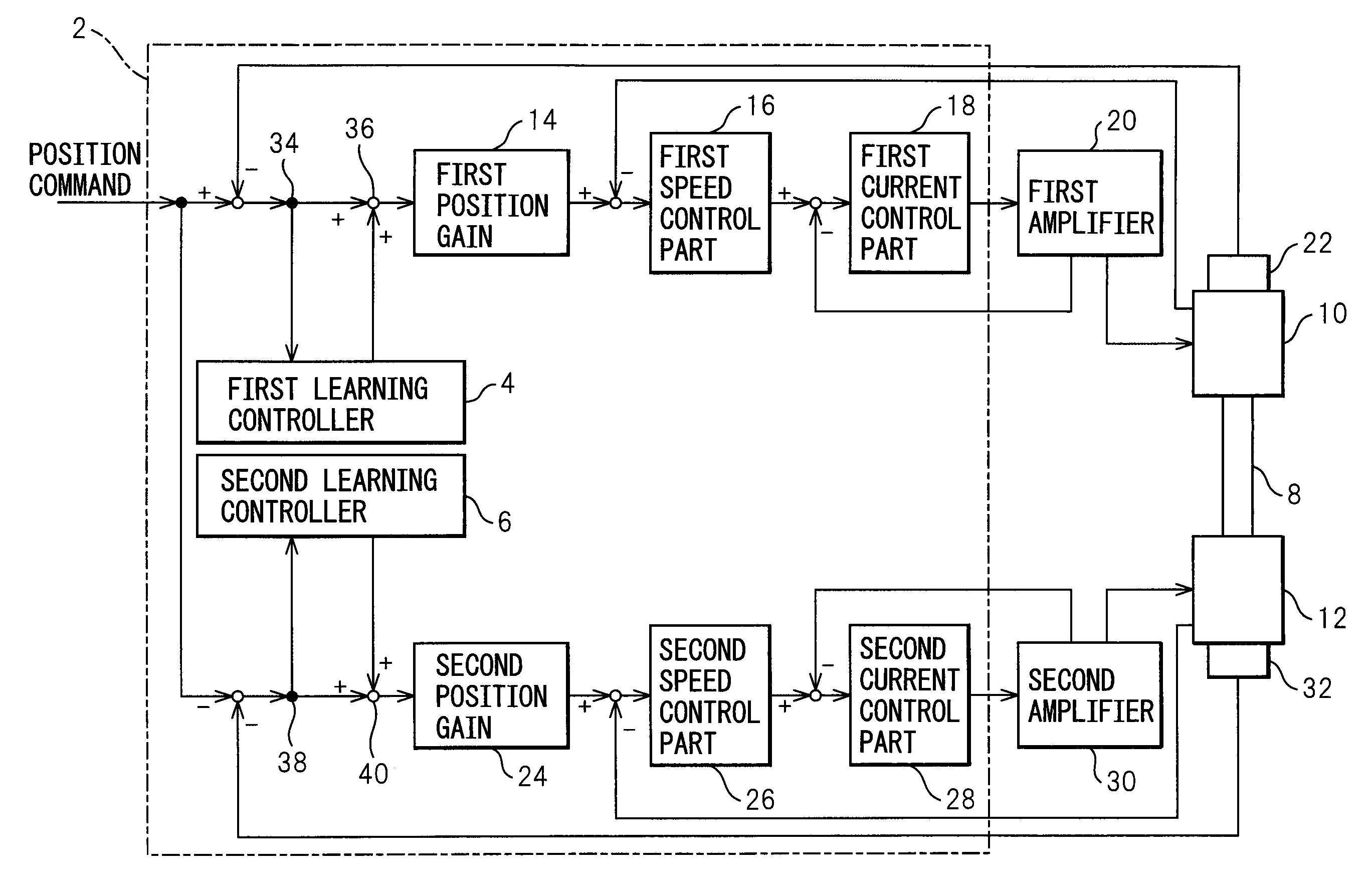
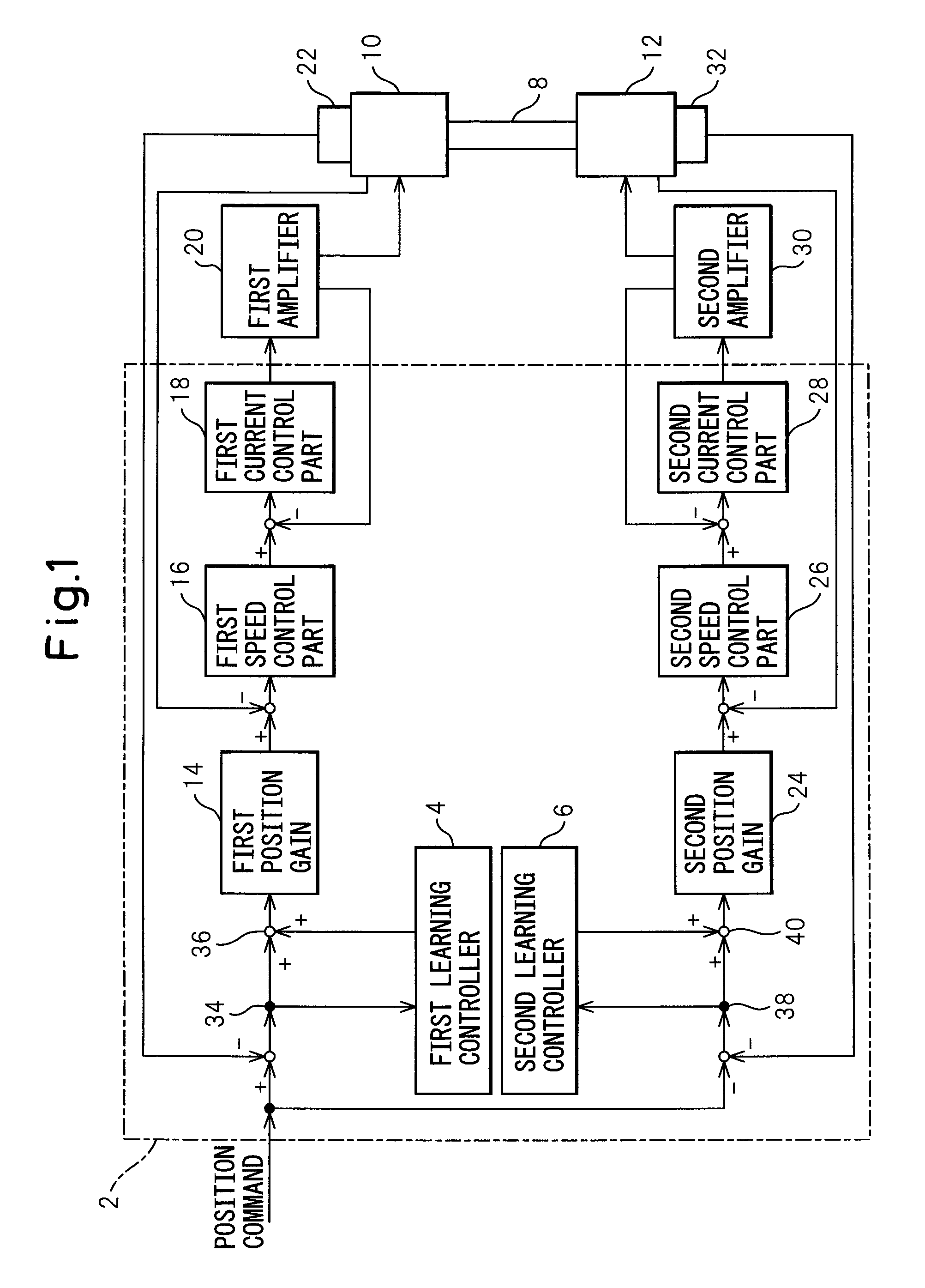
[0025]FIG. 1 is a block diagram of a control device 2 according to a first embodiment of the invention. Control device 2 is used for rotating a crankpin 8 by means of first and second electric motors 10 and 12. Control device 2 periodically outputs a command for controlling the electric motors.

[0026]In relation to first electric motor 10, when a position command (or a movement command) output from a numeric control device (not shown) is input to control device 2, a first position gain 14 outputs a speed command. Next, a first speed control part 16 outputs a torque command based on the speed command, a first current control part 18 outputs a voltage command based on the current command, and then a first amplifier 20 rotatably activates first electric motor 10. A first position detector 22 is attached to first electric motor 10 and a detected value from first position detector 22 is used for position feedback. Speed feedback and current feedback are also used for controlling the speed...


PUM


Abstract

A control device for electric motors, capable of precisely moving one object by using two electric motors based on periodically repeated commands. The control device includes a first learning controller for calculating an amount of correction so that a positional deviation of a first electric motor is minimized, and a second learning controller for calculating an amount of correction so that a positional deviation of a second electric motor is minimized. The first and second learning controllers are independent from each other, and configured to minimize the positional deviation of the corresponding electric motor. The parameters set in the learning controllers, each defining the response of learning control of each electric motor, are equal to each other.

Description

RELATED APPLICATIONS[0001]The present application claims priority from Japanese Patent Application No. 2007-274131, filed on Oct. 22, 2007, the entire content of which is fully incorporated herein by reference.BACKGROUND OF THE INVENTION[0002]1. Field of the Invention[0003]The present invention relates to a control device with a learning function, for driving a plurality of electric motors so as to move an object to be moved.[0004]2. Description of the Related Art[0005]In a machine such as a machine tool or an industrial machine, in the case that an object or a workpiece, having relatively low stiffness, such as a thin pin or a thin plate needs be moved, if a force for moving the workpiece is applied to a part of the workpiece which is far from the center of gravity of the workpiece, the workpiece may be bent or twisted, whereby it may be difficult to precisely move the workpiece. In such a case, by using two electric motors for moving the different parts of one workpiece, the workp...

Claims


Application Information

Patent Timeline
Patent Type & Authority Applications(United States)
IPC IPC(8): G05B13/02H02P5/00H02P5/46H02P5/54H02P29/00
CPCG05B19/404G05B2219/50227G05B2219/42152
Inventor OKITA, TADASHITOYOZAWA, YUKIOSONODA, NAOTO
Owner FANUC LTD
Why Eureka
Try Eureka