
Signal encoding apparatus and signal encoding method, and signal decoding apparatus and signal decoding method

Active Publication Date: 2007-04-17
SONY CORP
View PDF23 Cites 48 Cited by
  • Summary
  • Abstract
  • Description
  • Claims
  • Application Information

AI Technical Summary

Benefits of technology

[0011]The present invention has been proposed in view of such conventional actual circumstances, and its object is to provide a signal encoding apparatus and a method therefor which can generate optimum harmonic wave (higher harmonic) at a frequency band extended at the time of decoding even in the case where complicated harmonic wave exists, a signal decoding apparatus and a method therefor which decode code trains outputted from the signal encoding apparatus, a program for allowing computer to execute such signal encoding processing and signal decoding processing, and a computer readable recording medium where such program is recorded.

Problems solved by technology

However, in such efficient compression technology, since design and standardization are made in the state where bit rate and sound quality are clearly determined as target, when bit rate is further lowered while maintaining standard (format), sound quality is extremely deteriorated.
The technologies as stated above have the merit that change of format is not required so that it is sufficient to perform improvement only at the decoding side, but do not exhibit dramatic effect in point of sound quality because there is a necessity to extend the frequency band only from received signal, and are such that distortion from viewpoint of auditory sense is offensive to the ears in the high frequency band particularly in the case where there does not so exist correlation between low frequency band and high frequency band, etc. in dependency upon inputted sound source.
Since it is rare that plural pitches exist in the case of sound (speech) for telephone use, whereas there are many instances where plural pitches are included in the case of general audio signal, employment of such method is not effective, and there are many cases where pitch analysis does not function from the beginning.

Method used


Image

  • Signal encoding apparatus and signal encoding method, and signal decoding apparatus and signal decoding method
  • Signal encoding apparatus and signal encoding method, and signal decoding apparatus and signal decoding method
  • Signal encoding apparatus and signal encoding method, and signal decoding apparatus and signal decoding method

Examples


Embodiment Construction

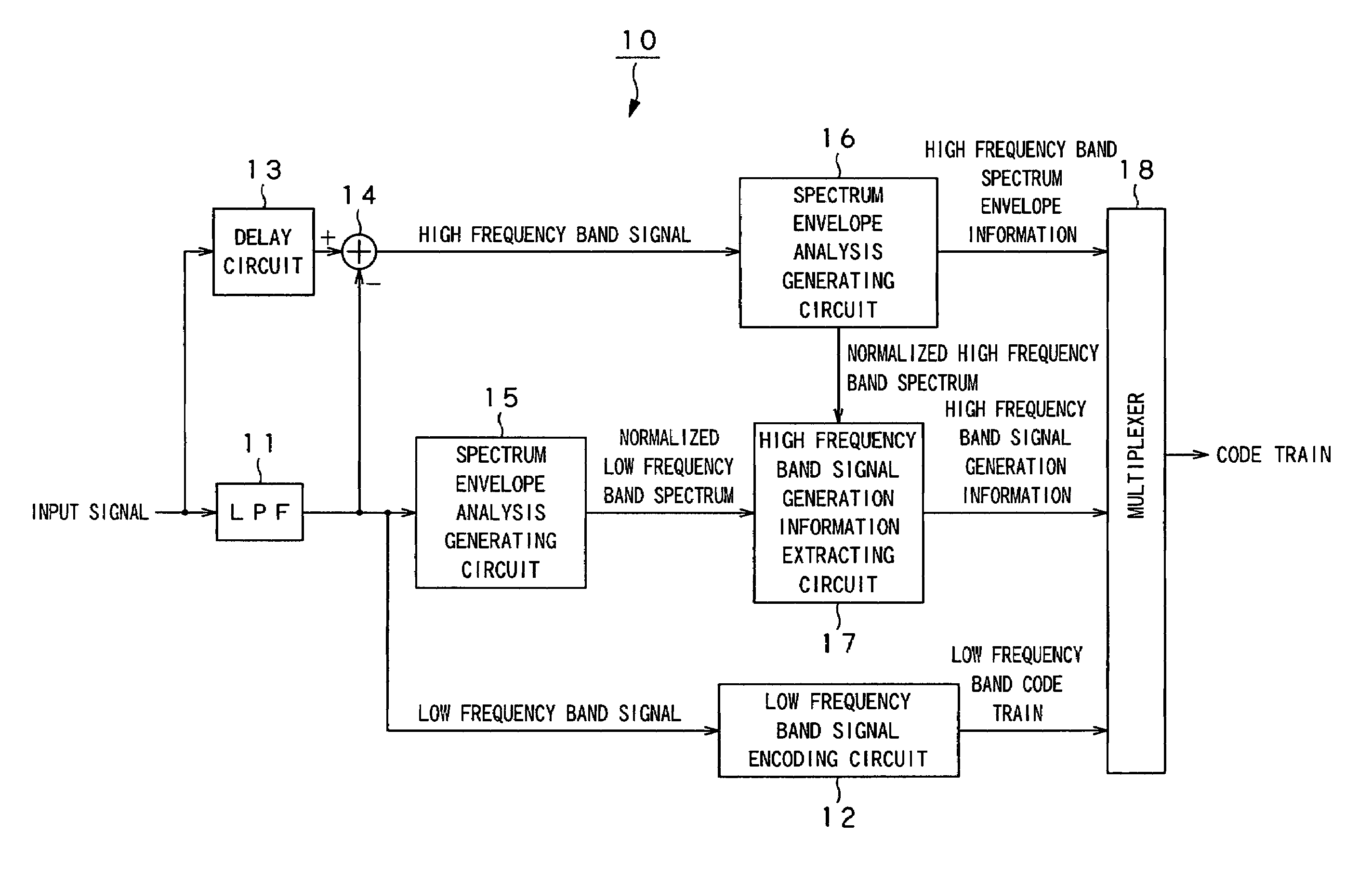
[0033]Explanation will be given below in detail with reference to the attached drawings in connection with practical embodiments to which the present invention is applied. In the embodiments, the present invention is applied to a signal encoding apparatus and a method therefor which limit inputted time series signal to low frequency band (low frequency band signal), and a signal decoding apparatus and a method therefor which extend that time series signal to high frequency band (high frequency band signal) by using mapping of low frequency band spectrum on the frequency axis, e.g., aliasing or shift (parallel displacement).

[0034]Simply speaking, in this embodiment, while limiting an inputted time series signal to a low frequency band signal having a predetermined cut-off frequency fc or less at the encoding side, aliasing frequency fa or shift frequency fsh, etc. used for generation of high frequency band signal at the decoding side is adaptively determined. Further, at the decoding...


PUM


Abstract

A signal encoding apparatus (10) limits an inputted time series signal to a low frequency band signal having a certain cut-off frequency or less to include the low frequency band signal into code train for outputting encoded low frequency band code train. In addition, the signal encoding apparatus (10) adaptively determines aliasing frequency fa, shift frequency fsh or tone•noise synthesis information r used for generation of high frequency band signal at the decoding side to include these information into code train outputted along with high frequency band spectrum envelope information as high frequency band generation information. A signal decoding apparatus generates a high frequency band signal from a low frequency band signal by using high frequency band signal generation information included in code train and high frequency band spectrum envelope to add the generated high frequency band signal and the low frequency band signal to thereby output a time series signal extended up to the high frequency band signal.

Description

BACKGROUND OF THE INVENTION[0001]The present invention relates to a signal encoding apparatus and a method therefor, a signal decoding apparatus and a method therefor, a program and a recording medium which are suitable when used in the case where time series signal limited to frequency band which is the encoding side is extended to signal in broader frequency band at the decoding side.[0002]This Application claims priority of Japanese Patent Application No. 2002-241052, field on Aug. 21, 2002, the entirety of which is incorporated by reference herein.[0003]In recent years, in efficient encoding of audio signal, mechanism of auditory sense of the human being is utilized to thereby have ability to compress data quantity having sound quality corresponding to CD (Compact Disk) into data quantity of about 1 / 10 of the original CD. At present, goods utilizing theses technologies are circulated also on the market, and it is realized that audio signals are recorded on smaller recording medi...

Claims


Application Information

Patent Timeline
IPC IPC(8): H03M7/00G10L19/02H03M7/30
CPCG10L21/038G10L19/0204H03M7/30G10L19/02
Inventor HONMA, HIROYUKIMATSUMOTO, JUN
Owner SONY CORP
Learn More