Optical disk recording/reproducing device

Inactive Publication Date: 2007-04-17
PANASONIC CORP
View PDF8 Cites 1 Cited by
  • Summary
  • Abstract
  • Description
  • Claims
  • Application Information

AI Technical Summary

Benefits of technology

[0012]It is an object of the present invention to provide an optical disk recording/reproducing device that allows an average driving current f

Problems solved by technology

As a result of this, power consumption is increased, and thus in portable equipment, the continuous operation time is shortened, which has been di

Method used


Image

  • Optical disk recording/reproducing device
  • Optical disk recording/reproducing device
  • Optical disk recording/reproducing device

Examples


embodiment 1

[0038](Embodiment 1)

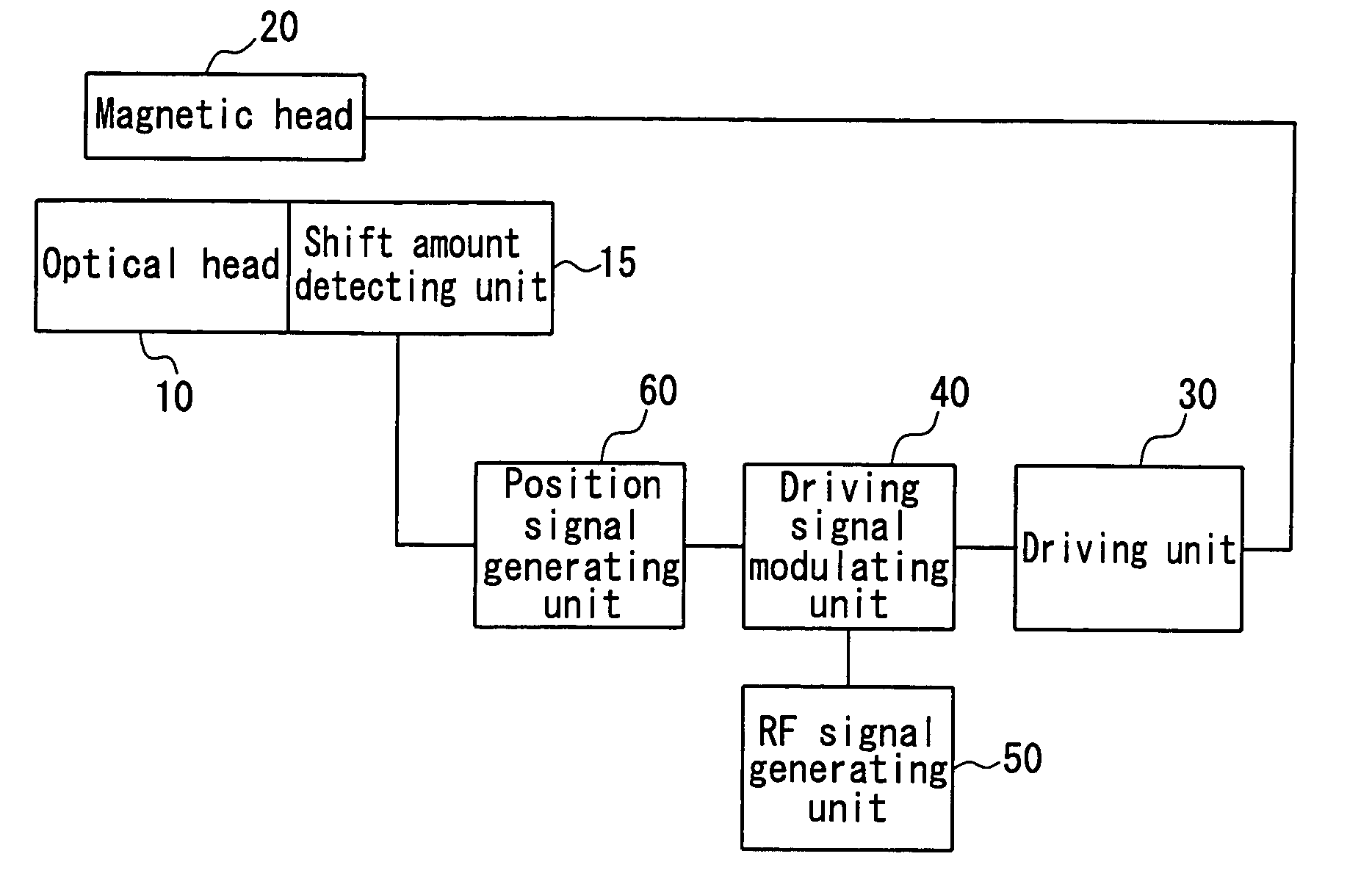
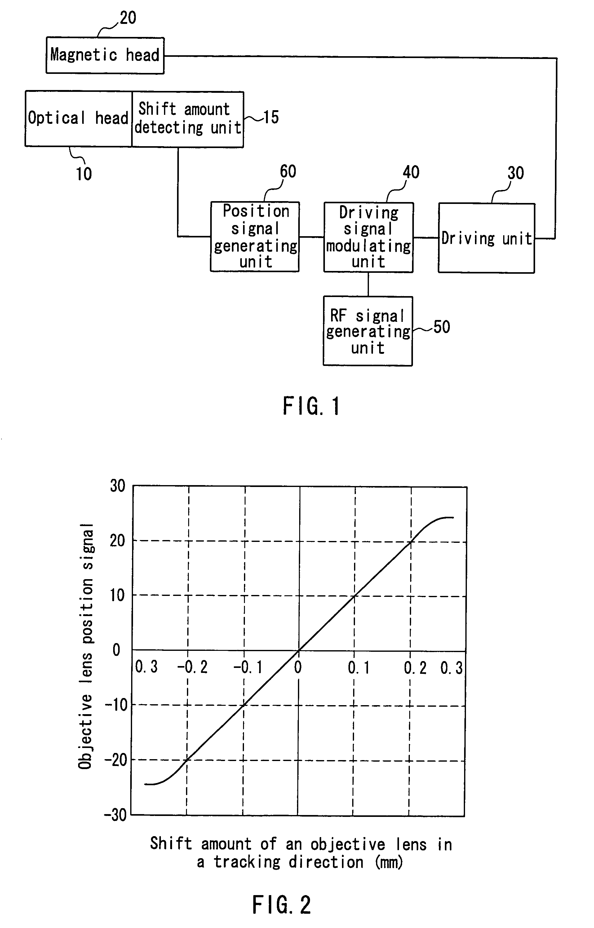
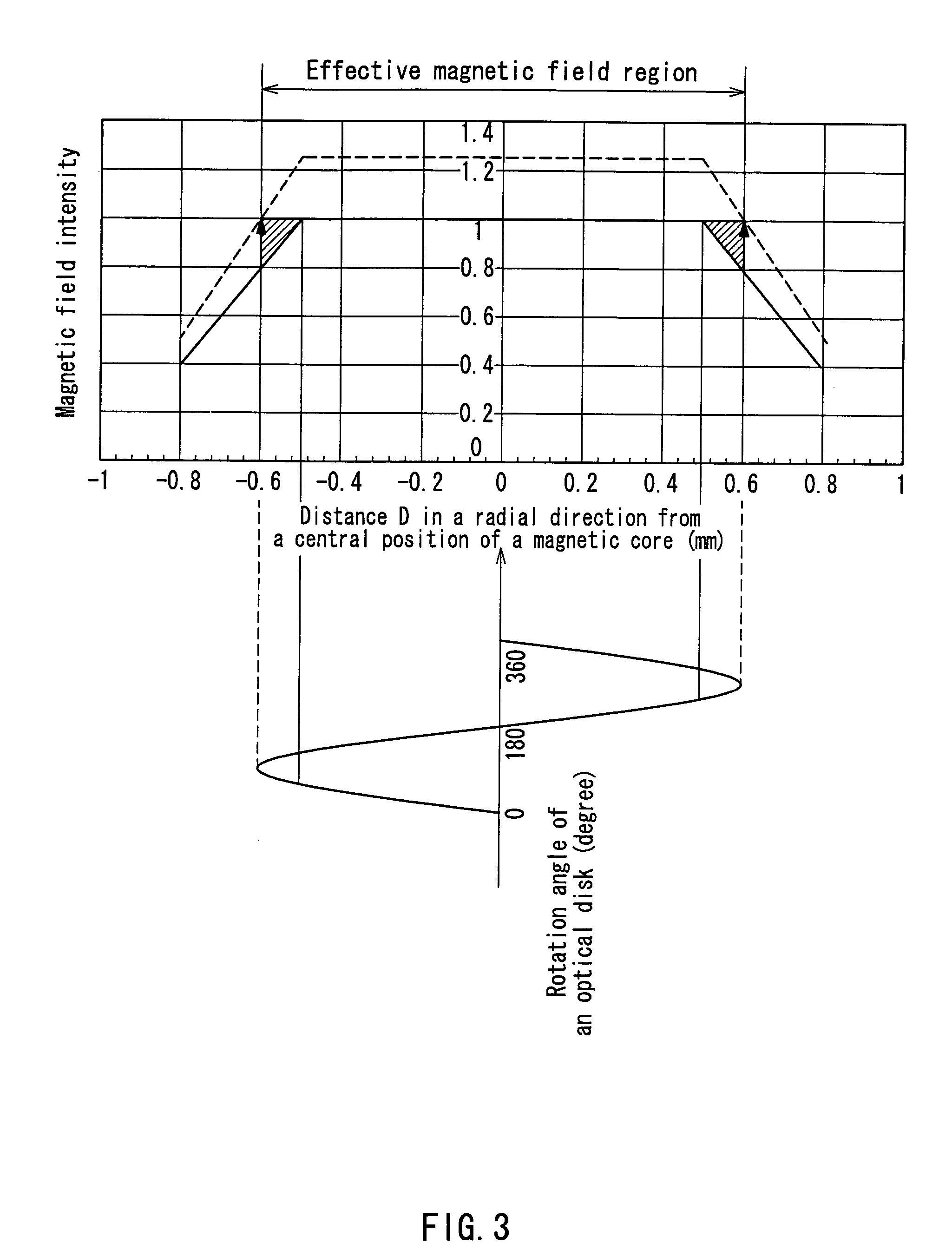
[0039]The following description is directed to an optical disk recording / reproducing device according to Embodiment 1 of the present invention with reference to FIGS. 1 to 6. FIG. 1 is a block diagram for explaining the optical disk recording / reproducing device according to this embodiment. FIG. 2 is a diagram showing a relationship between a shift amount of an objective lens in a tracking direction (radial direction) and an objective lens position signal in the optical disk recording / reproducing device according to this embodiment. FIG. 3 is a diagram showing the distribution of a magnetic field intensity in the radial direction. FIG. 4 is a diagram showing the driving current peak waveform in the optical disk recording / reproducing device according to this embodiment. FIG. 5 is a diagram showing a driving current pulse waveform.

[0040]As shown in FIG. 1, an objective lens actuator of an optical head 10 shifts the objective lens in the tracking direction so that t...

embodiment 2

[0053](Embodiment 2)

[0054]The description is directed to the configuration and operation according to Embodiment 2 of the present invention with reference to FIG. 7. FIG. 7 is a plan view of an optical head and a magnetic head according to this embodiment. In FIG. 7, like reference characters indicate like members whose functions and operations are the same as those of the members shown in FIG. 14, for which detailed descriptions are omitted.

[0055]Reference character 9 denotes a reflective-type photointerruptor housing a light-emitting diode and a phototransistor. The photointerruptor 9 functions as a unit that detects a shift amount of an objective lens 5 in a tracking direction. The photointerruptor 9 is placed on an actuator base 4d that is a member on a fixed side of an objective lens actuator 4 so as to be opposed to a member on a movable side of the objective lens actuator, which holds the objective lens 5. When the objective lens 5 is shifted in the tracking direction by the ...

embodiment 3

[0058](Embodiment 3)

[0059]The description is directed to the configuration and operation according to Embodiment 3 of the present invention with reference to FIGS. 8, 9A, 9B and 9C. FIG. 8 is a plan view of an optical head and a magnetic head according to this embodiment. FIGS. 9A, 9B and 9C are schematic diagrams for showing a photodetector.

[0060]In FIGS. 8, 9A, 9B and 9C, like reference characters indicate like members whose functions and operations are the same as those of the members shown in FIG. 14, for which detailed descriptions are omitted.

[0061]This embodiment differs from Embodiment 2 having a configuration shown in FIG. 7 in that instead of using the photointerruptor 9 used in Embodiment 2, a light receiving / emitting element 1 is used as a unit (not shown) that detects a shift amount of an objective lens in a tracking direction.

[0062]In FIGS. 9A, 9B and 9C, reference character 1a denotes a photodetector that is housed in the light receiving / emitting element 1, reference ...


PUM


Abstract

A moved distance detecting means (15) detects the moved distance in a tracking direction of an object lens, a position signal generating means (60) generates a position signal corresponding to the position of the object lens based on the detection, and a drive signal modulating means (40) modulates the drive current of a magnetic head (20) according to this position signal. Therefore, a drive current can be controlled according to the moved distance of the object lens to enable the magnetic head to be driven with a small current when a moved distance is small and with a large current according to a moved distance only when it is large, whereby it is possible to reduce an average drive current and hence reduce power consumption as a whole.

Description

TECHNICAL FIELD[0001]The present invention relates to an optical disk recording / reproducing device that performs optical information recording / reproduction.BACKGROUND ART[0002]It is said that today is the age of information, and high-density and large-capacity memories at the heart thereof have been developed enthusiastically. Memories are required to have not only the capability of high-density and large-capacity storage, but also the capability of achieving high reliability, rewriting capability and the like. Among recording media that satisfy these requirements, optical disk memories such as a magneto-optical disk and the like have received the most attention. The present invention relates to an optical disk recording / reproducing device that performs recording or reproduction with respect to such optical disk memories.[0003]Conventionally, many technical reports have been made on optical disk recording / reproducing devices. The following description will be made with reference to ...

Claims


Application Information

Patent Timeline
IPC IPC(8): G11B7/00G11B11/00G11B11/105
CPCG11B11/10508G11B11/10534G11B11/10573G11B11/10576G11B11/10595
Inventor TAKASIMA, MAKOTO
Owner PANASONIC CORP
Why Eureka
Try Eureka