

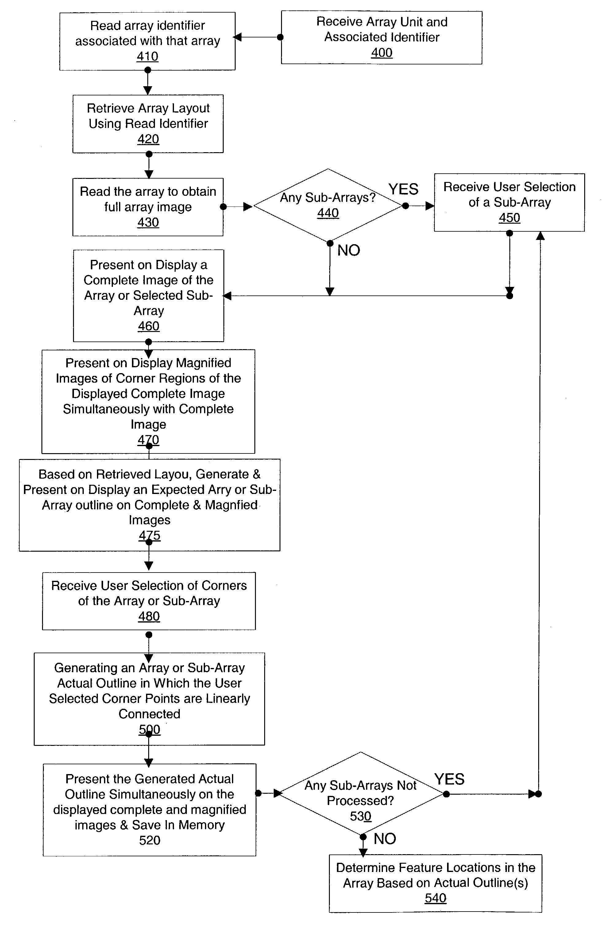
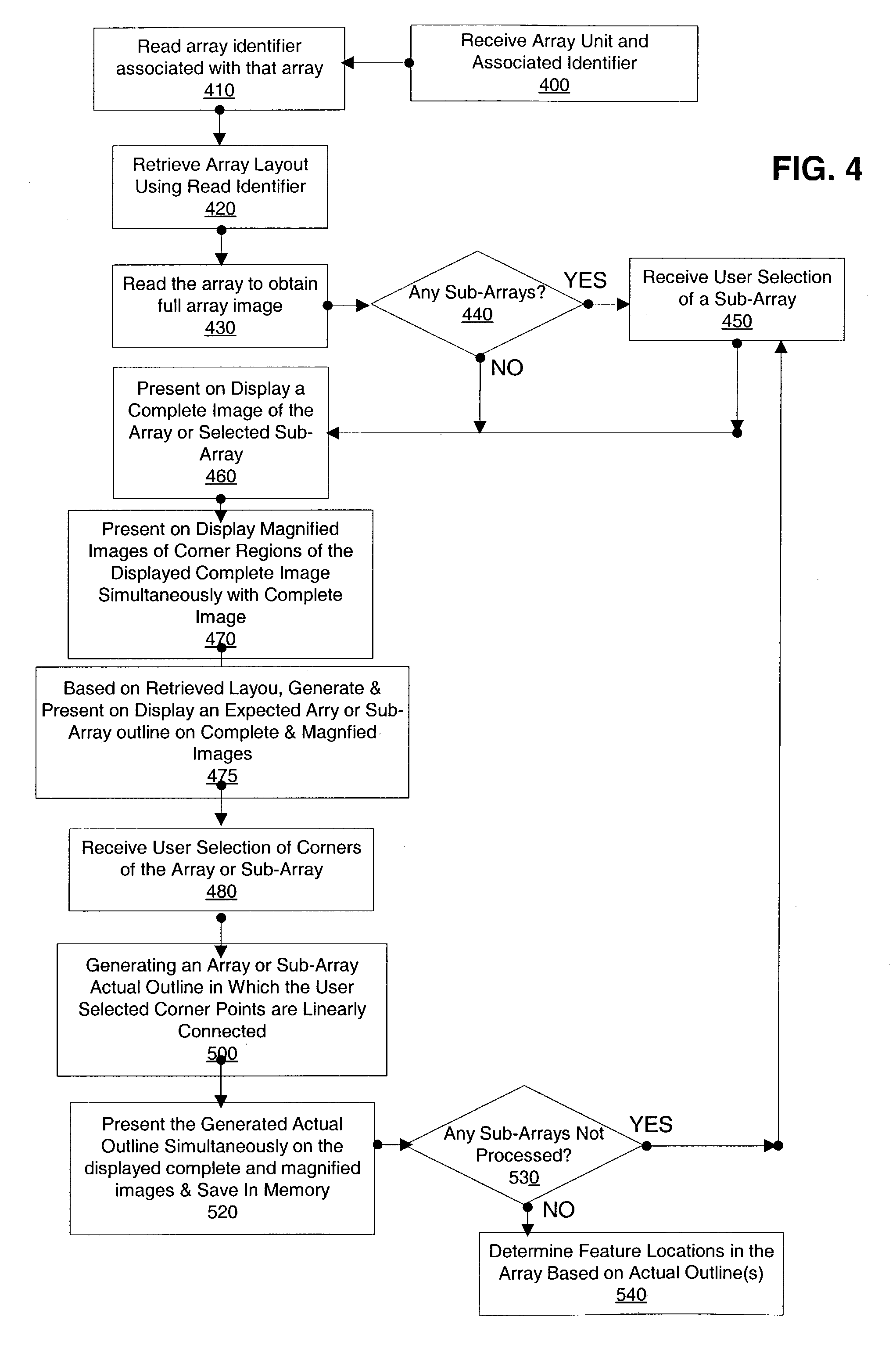
Feature locations in array reading
a feature location and array technology, applied in the field of arrays, can solve the problems of difficult to decide whether a given pixel belongs to a given feature, difficult task, expensive probes formed at each feature, etc., and achieve the effect of accurate location
- Summary
- Abstract
- Description
- Claims
- Application Information
AI Technical Summary
Benefits of technology
Problems solved by technology
Method used
Image

Examples
Embodiment Construction
[0019]Throughout the present application, unless a contrary intention appears, the following terms refer to the indicated characteristics.
[0020]A “biopolymer” is a polymer of one or more types of repeating units. Biopolymers are typically found in biological systems and particularly include polysaccharides (such as carbohydrates), and peptides (which term is used to include polypeptides, and proteins whether or not attached to a polysaccharide) and polynucleotides as well as their analogs such as those compounds composed of or containing amino acid analogs or non-amino acid groups, or nucleotide analogs or non-nucleotide groups. This includes polynucleotides in which the conventional backbone has been replaced with a non-naturally occurring or synthetic backbone, and nucleic acids (or synthetic or naturally occurring analogs) in which one or more of the conventional bases has been replaced with a group (natural or synthetic) capable of participating in Watson-Crick type hydrogen bon...
PUM
 Abstract
Description
Claims
Application Information