
System and method for scheduling transmission from multiple-beam transmitters

Active Publication Date: 2007-04-17
BLACKBERRY LTD
View PDF10 Cites 31 Cited by
  • Summary
  • Abstract
  • Description
  • Claims
  • Application Information

AI Technical Summary

Benefits of technology

[0024]In some embodiments, the method further comprises at a beginning of scheduling for ea

Problems solved by technology

A challenge for WTTN is to provide constant bit rate transmission to each LAP.
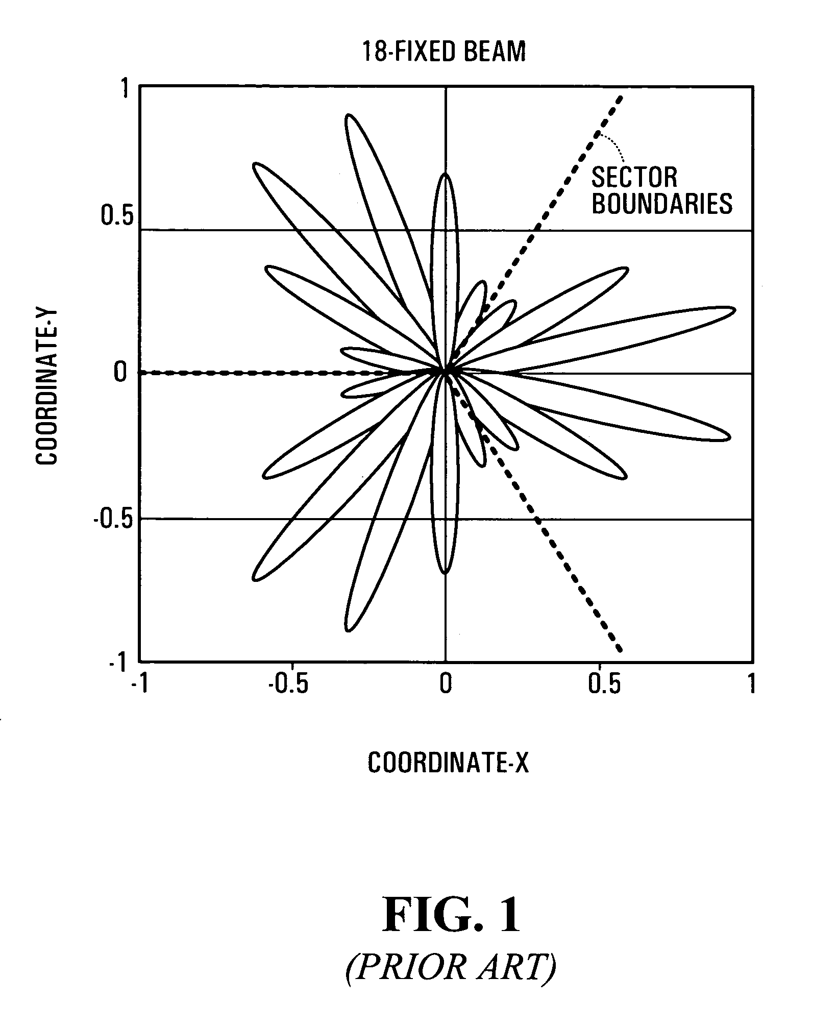
In the fixed beam method described with reference to FIG. 1, there are two problems.
The first problem is that the number of receivers assigned into each beam is not balanced resulting in unequal throughput for each receiver.
The second problem occurs when a receiver is located near the boundary of two beams.
This results in a dead spot where the receiver cannot be served with a required minimum data rate.
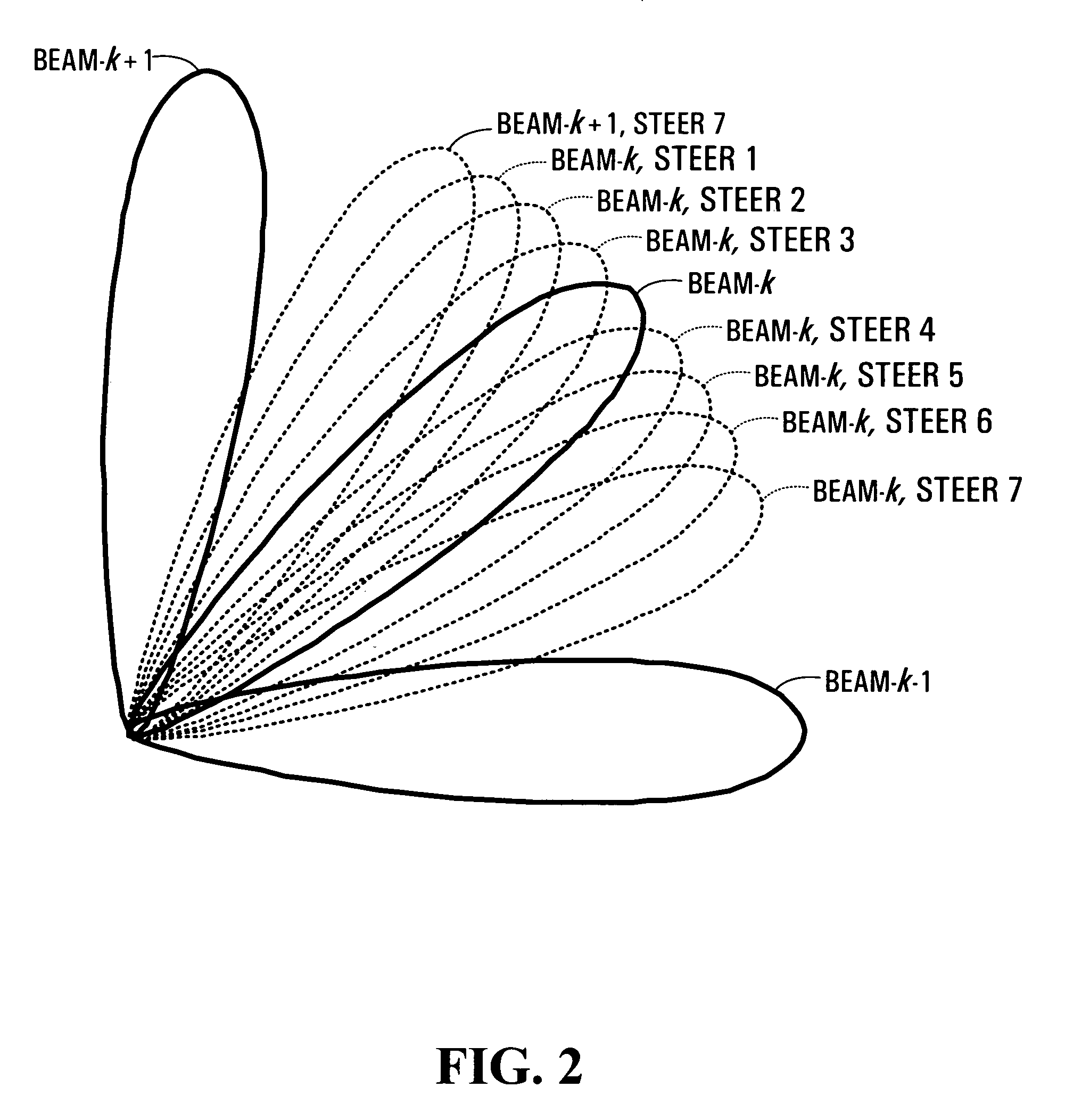
The problem for adaptive beamforming is that the beams formed by the antenna array could collide with each other when two receivers are closely located, resulting an extremely low SNR in receiver.
The conventional round robin or random scheduling solutions fail to meet guaranteed CBR (constant bit rate) requirements.

Method used


Image

  • System and method for scheduling transmission from multiple-beam transmitters
  • System and method for scheduling transmission from multiple-beam transmitters
  • System and method for scheduling transmission from multiple-beam transmitters

Examples


Embodiment Construction

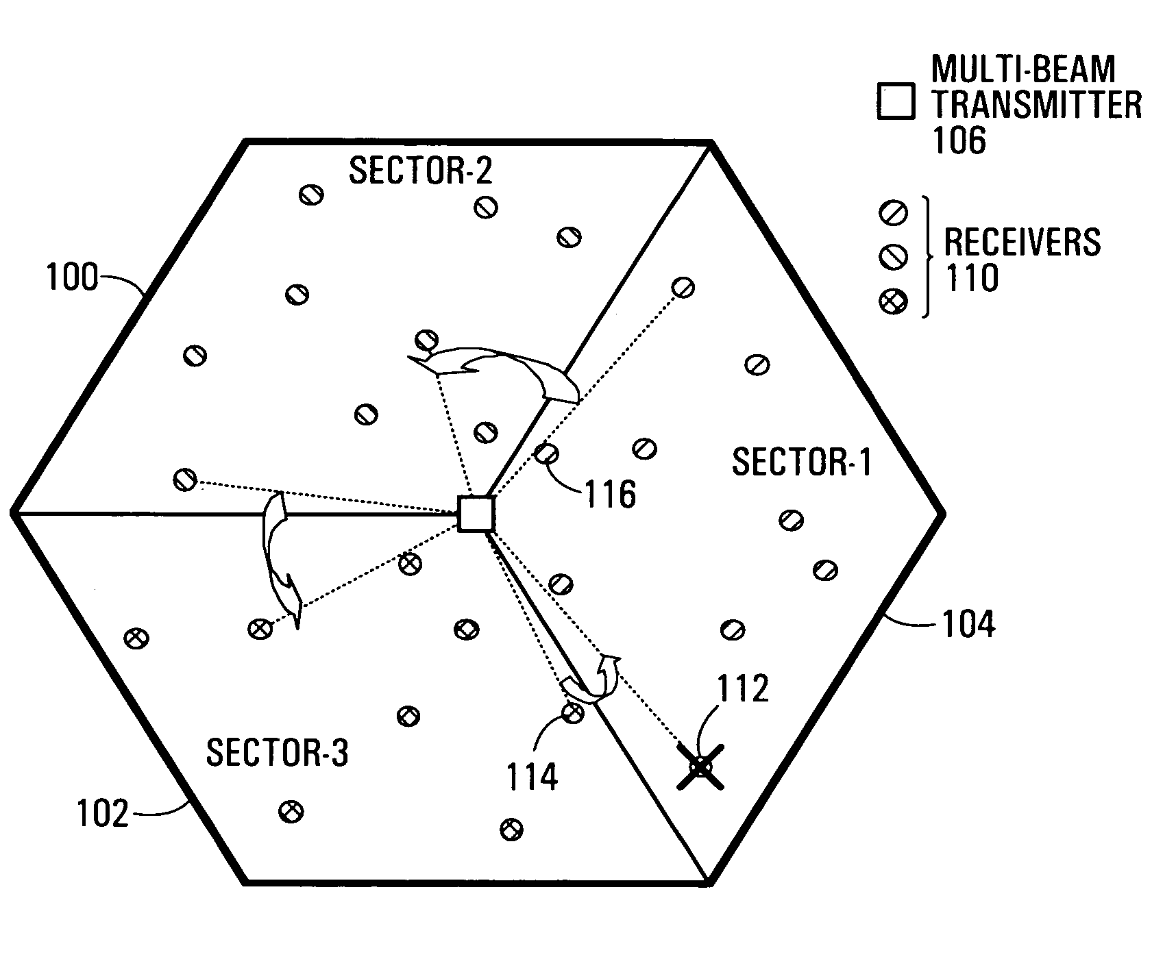
[0053]System performance with adaptive beamforming depends strongly upon a scheduler under multi-receiver conditions. This is because the adaptive beamformer has no knowledge to separate the receivers in space that may be very close each other. Receivers that are close each other and are scheduled at the same time could cause serious interference between each other. This in turn can have an effect on data transmission rates, and in particular may result in some receivers not achieving a specified minimum data transmission rate. To avoid such impacts on data transmission, a system and method for scheduling is provided which assigns such receivers in different time slots so as to improve the system capacity.

[0054]A method of scheduling transmission by a multi-beam transmitter to a plurality of receivers will now be described with reference to FIG. 4, which is a flowchart of a first method provided by an embodiment of the invention. The method begins at step 4-1 with the determination ...


PUM


Abstract

Systems and methods for scheduling transmissions from multi-beam transmitters to sets of receivers are provided. An angle of departure is determined for each of the receivers, and the transmissions to the receivers is then scheduled on the basis of the separation between the angles of departure between the receivers. For example, a constraint may be imposed that no two receivers having an angle of departure separated by less than a first minimum will be scheduled during an even scheduling interfold. Some implementations include a prioritized scheduling system in which high priority receivers are scheduled according to a performance metric subject to the angle departure constraint, and subsequently low priority receivers as scheduled only subject to the angle departure constraint.

Description

RELATED APPLICATIONS[0001]This application claims the benefit of U.S. Provisional Application No. 60 / 517,637 filed Nov. 6, 2003.FIELD OF THE INVENTION[0002]The invention relates to signal transmission over multiple partially interfering beams.BACKGROUND OF THE INVENTION[0003]Systems employing wireless to the network (WTTN) can now deliver the same data rate as fiber to the network (FTTN) solutions. These systems provide point to multi-point connections at giga-bit rate levels. However, an advantage of the wireless approach to the fiber approach is that WTTN can achieve a cost of approximately one quarter that of FTTN.[0004]In one example system implementation, a network access point (NAP) is provided which serves a set of local access points (LAP) via wireless point-to-point connection. Each local access point in turn provides service to a localized set of customers. A challenge for WTTN is to provide constant bit rate transmission to each LAP. One reason for this is that wireless l...

Claims


Application Information

Patent Timeline
IPC IPC(8): H04M1/00H01Q3/00H04B7/185H04Q7/20H04W16/28
CPCH04W16/28
Inventor WU, JIANMINGZHU, PEIYINGTONG, WEN
Owner BLACKBERRY LTD
Learn More