Fuel oil injector

A technology of injectors and fuel oil, which is applied in the direction of fuel injection devices, machines/engines, and charging systems, and can solve problems such as aggravating the wet wall effect, uneven gas mixing, and affecting engine power, economy, and environmental protection. , to avoid the wet wall effect, improve the economy and environmental protection of emissions, and achieve the effect of excellent fuel atomization

Inactive Publication Date: 2007-01-31
BYD CO LTD
View PDF0 Cites 2 Cited by
  • Summary
  • Abstract
  • Description
  • Claims
  • Application Information

AI Technical Summary

Problems solved by technology

[0002] In order to improve the air charge coefficient of the engine, enhance power, and reduce emissions, multi-intake valve structures such as four-valve and five-valve are widely used in engines, and traditional single-hole fuel injectors are gradually replaced by multi-hole fuel injectors. However, although the porous fuel injec

Method used


Image

  • Fuel oil injector
  • Fuel oil injector
  • Fuel oil injector

Examples


Embodiment 1

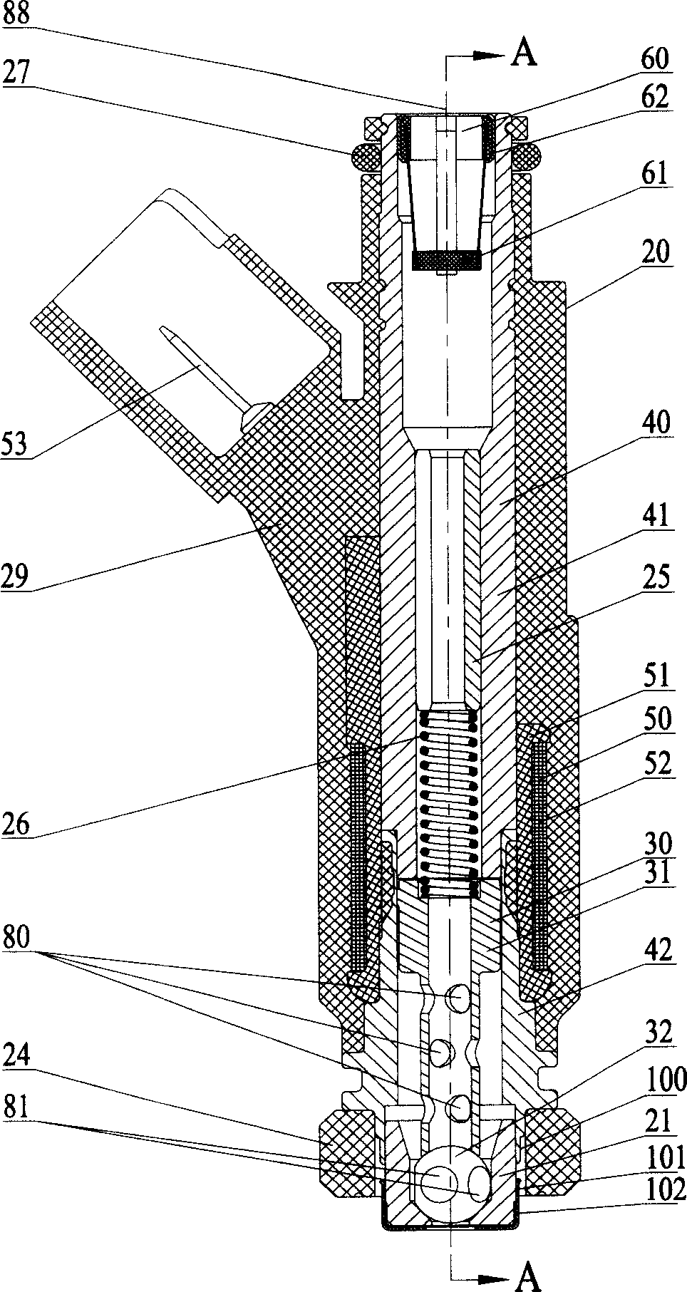
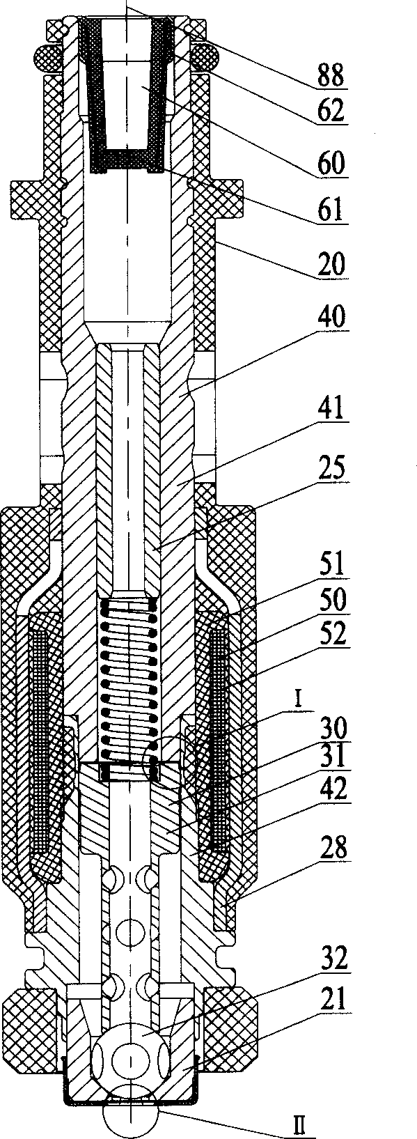
[0021] Embodiment one: Figure 1-11 It is a general structure and configuration of a fuel injector 20 using the technical solution of the present invention, and this example is designed for a four-valve engine. Such as Figure 1 to Figure 4 As shown, it includes valve body assembly 40, ball valve assembly 30, coil assembly 50, filter cup assembly 60, valve seat 21, orifice plate 22, anti-carbon plate 23, support plate 24, adjustment sleeve 25, spring 26, seal Ring 27, protective sheet 28, injection molded housing 29. All the above-mentioned components and parts share a longitudinal axis 88 .

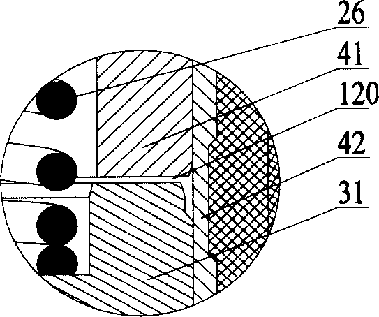
[0022] to combine figure 1 , 2 , 3, the valve body assembly 40 includes an upper valve body 41 and a lower valve body 42, which are welded by laser. They are not only structural parts, but also important functional parts in the magnetic circuit, so they are all processed by materials with high magnetic permeability. made. The ball valve assembly 30 includes an iron core 31 and a va...

Embodiment 2

[0034] Embodiment two: Figure 12 and Figure 13 Another embodiment of an orifice plate is disclosed. There are six nozzle holes on the nozzle hole plate, which are divided into two groups, namely the first group of nozzle holes (121, 122, 123) and the second group of nozzle holes (124, 125, 126). 216 is the plane where the centers of the two intake valve openings are located, and this plane is perpendicular to the axis 213 of the orifice plate. 217 and 218 are the center points of the first and second intake valve ports respectively. Points 231, 233, 235, 237, 239, and 241 are located on the plane 216, and 231, 233, and 235 are three points uniformly distributed on a circle centered on point 217; Three points evenly spaced on a circle. 230, 232, 234, 236, 238, 240 are six points uniformly distributed on the circumference of the bottom surface 214 of the orifice plate. 215 is the axis of six spray holes, which respectively pass through 230-231, 232-233, 234-235, 236-237, ...


PUM


Abstract

There is disclosed a fuel injector, in which, on the orifice plate are distributed a plurality of orifices divided into several groups. Each group of orifices feeds the fuel for one corresponding air intake valve. By means of the design aimed at angles of departure, deviation and atomizer cone and using a multiple orifice zoning injection fuel-feeding method, the fuel is injected into the mouth of the corresponding air intake valve separately, so that the burning and running efficiency of engines has greatly raised.

Description

【Technical field】 [0001] The invention relates to a fuel injector of an electronically controlled fuel injection system. 【Background technique】 [0002] In order to improve the air charge coefficient of the engine, enhance power, and reduce emissions, multi-intake valve structures such as four-valve and five-valve are widely used in engines, and traditional single-hole fuel injectors are gradually replaced by multi-hole fuel injectors. However, although the porous fuel injector adopts multi-point injection for fuel supply, because it cannot partition the injected fuel, a large amount of fuel is sprayed on the partition wall between the two intake valve ports, which aggravates the wet wall effect, so that the gas is mixed. Unevenness affects the power, economy and emission environmental protection of the engine. 【Content of invention】 [0003] The object of the present invention is to provide an efficient and environment-friendly fuel injector structure in order to overcom...

Claims


Application Information

Patent Timeline
IPC IPC(8): F02M61/04
Inventor 蔡晓斌
Owner BYD CO LTD
Why Eureka
Try Eureka