Fuel oil injector
An injector and fuel technology, which is applied to fuel injection devices, machines/engines, charging systems, etc., can solve the problems of high manufacturing cost, parts accuracy, and high assembly process requirements, and achieve easy assembly accuracy, ensure assembly accuracy, parts reduced effect
- Summary
- Abstract
- Description
- Claims
- Application Information
AI Technical Summary
Problems solved by technology
Method used
Image
Examples
Embodiment 1
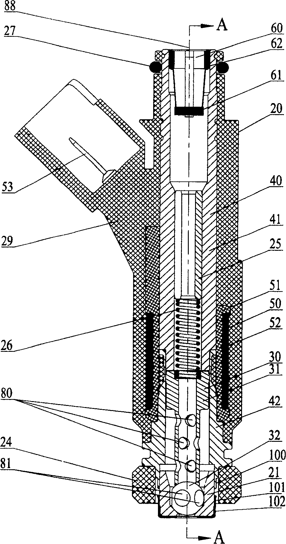
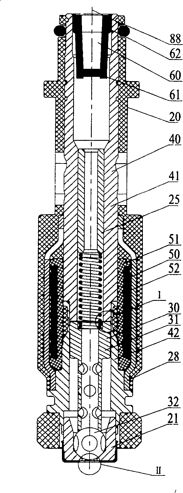
[0022] Embodiment one: Figure 1-11 It is a general structure and configuration of a fuel injector 20 using the technical solution of the present invention, and this example is designed for a four-valve engine. like Figure 1 to Figure 4 As shown, it includes valve body assembly 40, ball valve assembly 30, coil assembly 50, filter cup assembly 60, valve seat 21, orifice plate 22, anti-carbon plate 23, support plate 24, adjustment sleeve 25, spring 26, seal Ring 27, protective sheet 28, injection molded housing 29. All the above-mentioned components and parts share a longitudinal axis 88 .
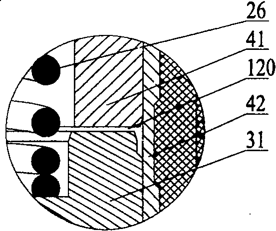
[0023] combine figure 1 , 2 , 3, the valve body assembly 40 includes an upper valve body 41 and a lower valve body 42, which are welded by laser. They are not only structural parts, but also important functional parts in the magnetic circuit, so they are all processed by materials with high magnetic permeability. made. The ball valve assembly 30 includes an iron core 31 and a valve ba...
Embodiment 2
[0035] Embodiment two: Figure 12 and Figure 13 Another embodiment of an orifice plate is disclosed. There are six nozzle holes on the nozzle hole plate, which are divided into two groups, namely the first group of nozzle holes (121, 122, 123) and the second group of nozzle holes (124, 125, 126). 216 is the plane where the centers of the two intake valve openings are located, and this plane is perpendicular to the axis 213 of the orifice plate. 217 and 218 are the center points of the first and second intake valve ports respectively. Points 231, 233, 235, 237, 239, and 241 are located on the plane 216, and 231, 233, and 235 are three points uniformly distributed on a circle centered on point 217; Three points evenly spaced on a circle. 230, 232, 234, 236, 238, 240 are six points uniformly distributed on the circumference of the bottom surface 214 of the orifice plate. 215 is the axis of six spray holes, which respectively pass through 230-231, 232-233, 234-235, 236-237, ...
PUM
 Abstract
Description
Claims
Application Information
 - R&D
- Intellectual Property
- Life Sciences
- Materials
- Tech Scout
- Unparalleled Data Quality
- Higher Quality Content
- 60% Fewer Hallucinations
Browse by: Latest US Patents, China's latest patents, Technical Efficacy Thesaurus, Application Domain, Technology Topic, Popular Technical Reports.
© 2025 PatSnap. All rights reserved.Legal|Privacy policy|Modern Slavery Act Transparency Statement|Sitemap|About US| Contact US: help@patsnap.com


