Method for ventilating a working machine, and such a working machine

a working machine and working machine technology, applied in the field of working machines, can solve the problems of insufficient ejector effect, too low exhaust gas speed, and high operating temperature in the engine compartmen

Inactive Publication Date: 2007-04-24
VOLVO CONSTR EQUIP HLDG (SWEDEN) AB
View PDF14 Cites 52 Cited by
  • Summary
  • Abstract
  • Description
  • Claims
  • Application Information

AI Technical Summary

Benefits of technology

[0008]The exhaust pipe opens inside the tailpipe, which in turn means that as they flow the exhaust gases expand to a greater volume, with the result that a certain ejector effect occurs in the area where the exhaust gases flow out of the exhaust pipe and into the tailpipe. The ejector effect or ejector action will contribute and lead to the air in the surrounding, annular gap being entrained by the exhaust gases out through the tailpipe into the surrounding atmosphere.
[0010]It is desirable to provide such a method and working machine wherein the principle of utilizing the ejector effect to ventilate air out of the engine compartment is used to better effect in comparison to the prior art. An aspect of the present invention proposes a method and a working machine, which in its practical application takes up relatively little space inside the engine compartment and which provides a robust and reliable solution to the problem of ventilating closed or at least substantially closed engine compartments.
[0012]Leading the air in centrally into an outlet duct, preferably formed by a tailpipe projecting from the engine hood, instead of leading the air into an annular gap surrounding the exhaust pipe, from which the exhaust gases are introduced into the outlet duct, as in the prior art, gives a stronger ejector effect. Compared to the prior art, a larger quantity of air can thereby by entrained by a given quantity of exhaust gases.
[0016]The air baffle element preferably forms an air baffle duct, the cross-section of which diminishes toward the point where it opens into the outlet duct. That is to say, the air baffle element is funnel-shaped. In this way air can be effectively entrained and led into the outlet duct.
[0019]The outlet duct in which the air baffle element extends is then defined by a wall, which has an inner periphery extending at a constant distance from the outer periphery of the air baffle element in the area where the wall and the air baffle element overlap one another. Air and exhaust gases thereby flow in a parallel direction into the common outlet duct. The air baffle element extends far enough from its engine compartment orifice to avoid a backflow of air (and exhaust gases) into the engine compartment via the air baffle duct of the air baffle element. The flow directions of the exhaust gases and the air as they enter the common part of the outlet duct are also designed to prevent such backflow.

Problems solved by technology

Usually, in conventional wheel loaders, the engine compartment is substantially closed and high operating temperatures therefore occur in the engine compartment.
However, its area should not be too large, since this would result in too low an exhaust gas speed and insufficient ejector effect when the gases are permitted to expand in the outlet duct.

Method used


Image

  • Method for ventilating a working machine, and such a working machine
  • Method for ventilating a working machine, and such a working machine
  • Method for ventilating a working machine, and such a working machine

Examples


Embodiment Construction

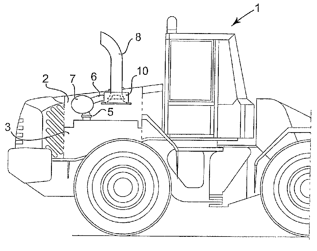
[0027]FIG. 1 shows a working machine 1 which typically is a conventional wheel loader, but might be any working machine which has a substantially closed engine compartment with a need for active ventilation during operation.

[0028]The working machine 1 comprises an engine compartment 2, an internal combustion engine 3 arranged in the engine compartment, and an engine hood or casing 4, which separates the engine compartment 2 from the surrounding atmosphere. The working machine 1 further comprises an exhaust system 5, via which exhaust gases are led from the engine 3 to the atmosphere. The exhaust system 5 comprises an exhaust pipe 6 and a silencer 7, together with a tailpipe 8, which extends outwards from the engine hood 4 and forms an outlet duct 9. The exhaust pipe 6 extends from the engine 3 via the silencer 7 up to the tailpipe 8.

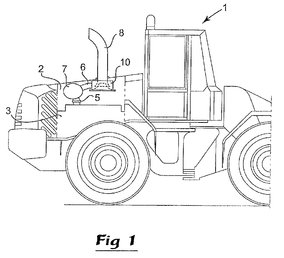
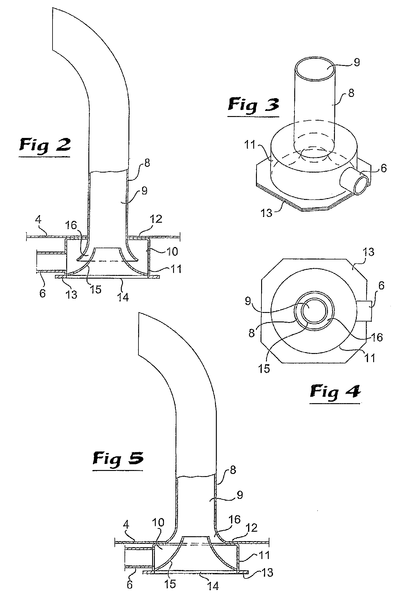
[0029]The exhaust pipe 6 opens into a chamber 10, which is formed by an essentially cylindrical side wall 11, an annular end wall 12 which is connected ...


PUM


Abstract

A working machine includes an engine compartment, an engine hood, an internal combustion engine arranged in the engine compartment and an exhaust system, which extends from the engine out of the engine compartment via the engine hood. The exhaust system is provided with an air intake for admitting air from the engine compartment into the exhaust system and entraining the air together with the exhaust gases. The air intake includes an air baffle element, which leads the air into an essentially central area in an outlet duct, in which the exhaust gases are led out, in such a way that the air is entrained out of the engine compartment by the exhaust gases through an ejector effect which the exhaust gases exert on the air in the outlet duct.

Description

[0001]The present invention is a continuation of PCT / SE2004 / 000494, filed Mar. 31, 2004, which claims priority to SE 0301123-6, filed Apr. 16, 2003, both of which are hereby incorporated by reference.BACKGROUND AND SUMMARY[0002]The present invention relates to a working machine, comprising an engine compartment, an engine hood, an internal combustion engine arranged in the engine compartment and an exhaust system which extends from the engine out of the engine compartment via the engine hood, the exhaust system being provided with an air intake for admitting air from the engine compartment into the exhaust system and entraining the air together with the exhaust gases.[0003]The invention also relates to a method of ventilating the engine compartment of such a working machine.[0004]The term working machine must be regarded as signifying and includes both stationary machines and vehicles. It relates in particular to machines with substantially closed engine compartment in which the tem...

Claims


Application Information

Patent Timeline
Patent Type & Authority Patents(United States)
IPC IPC(8): F01N3/02B62D25/10F01N3/22F01N13/08F01N13/20F01P1/00F01P5/08
CPCB62D25/10F01N13/082F01P5/08F01N3/22F01N2270/02F01N2590/08F01P2001/005
Inventor WILLIX, MICHAELBORJESSON, TORBJORNOLLILA, PEKKA
Owner VOLVO CONSTR EQUIP HLDG (SWEDEN) AB
Why Eureka
Try Eureka