Hydraulic and mechanical noise isolation for improved formation testing

a technology of mechanical noise isolation and formation testing, which is applied in the direction of fluid removal, survey, borehole/well accessories, etc., can solve the problems of significant time and money required for retrieving drill string and/or running a second test tool into the borehole, and the difficulty of using wire line tools for testing, etc., to achieve a quiet environment free of vibration and movement

Inactive Publication Date: 2007-04-24
BAKER HUGHES HLDG LLC
View PDF15 Cites 23 Cited by
  • Summary
  • Abstract
  • Description
  • Claims
  • Application Information

AI Technical Summary

Benefits of technology

[0017]An advantage of the present invention includes use of the pressure and resistivity sensors with the MWD system, to allow for real time data transmission of those measurements. Another advantage is that the present invention allows obtaining static pressures, pressure build-ups, and pressure draw-downs with the work string such as a drill string in place and in an extremely quiet environment free of vibration and movement.
includes use of the pressure and resistivity sensors with the MWD system, to allow for real time data transmission of those measurements. Another advantage is that the present invention allows obtaining static pressures, pressure build-ups, and pressure draw-downs with the work string such as a drill string in place and in an extremely quiet environment free of vibration and movement.

Problems solved by technology

Commercial development of hydrocarbon fields requires significant amounts of capital.
Regardless of the type of test tool and type of communication system used, the amount of time and money required for retrieving the drill string and / or running a second test tool into the borehole is significant.
Further, if the borehole is highly deviated, a wire line tool is difficult to use to perform the testing.
The typical MWD tool, however, suffers in that vibrations caused by flowing drilling fluid, mud pumps, drilling motors and surface equipment are transmitted to the test device through the drill string or even directly in the case of flowing drilling fluid.
These vibrations often adversely affect test results, because the downhole instrumentation can be too sensitive to operate effectively in mechanically noisy environment.
Another problem is associated with vertical movement known as heave encountered when drilling in an offshore environment.
Heave movement can cause pressure leaks where probe sealing pads and packers engage the borehole wall to form a seal.
Heave movement can also result in excessive wear on soft materials used for sealing against the borehole wall.
Although such heave is normally associated with offshore drilling, any unwanted vertical movement while a seal is engaged with the borehole wall can damage the seal material or cause unwanted leaks.

Method used


Image

  • Hydraulic and mechanical noise isolation for improved formation testing
  • Hydraulic and mechanical noise isolation for improved formation testing
  • Hydraulic and mechanical noise isolation for improved formation testing

Examples


Embodiment Construction

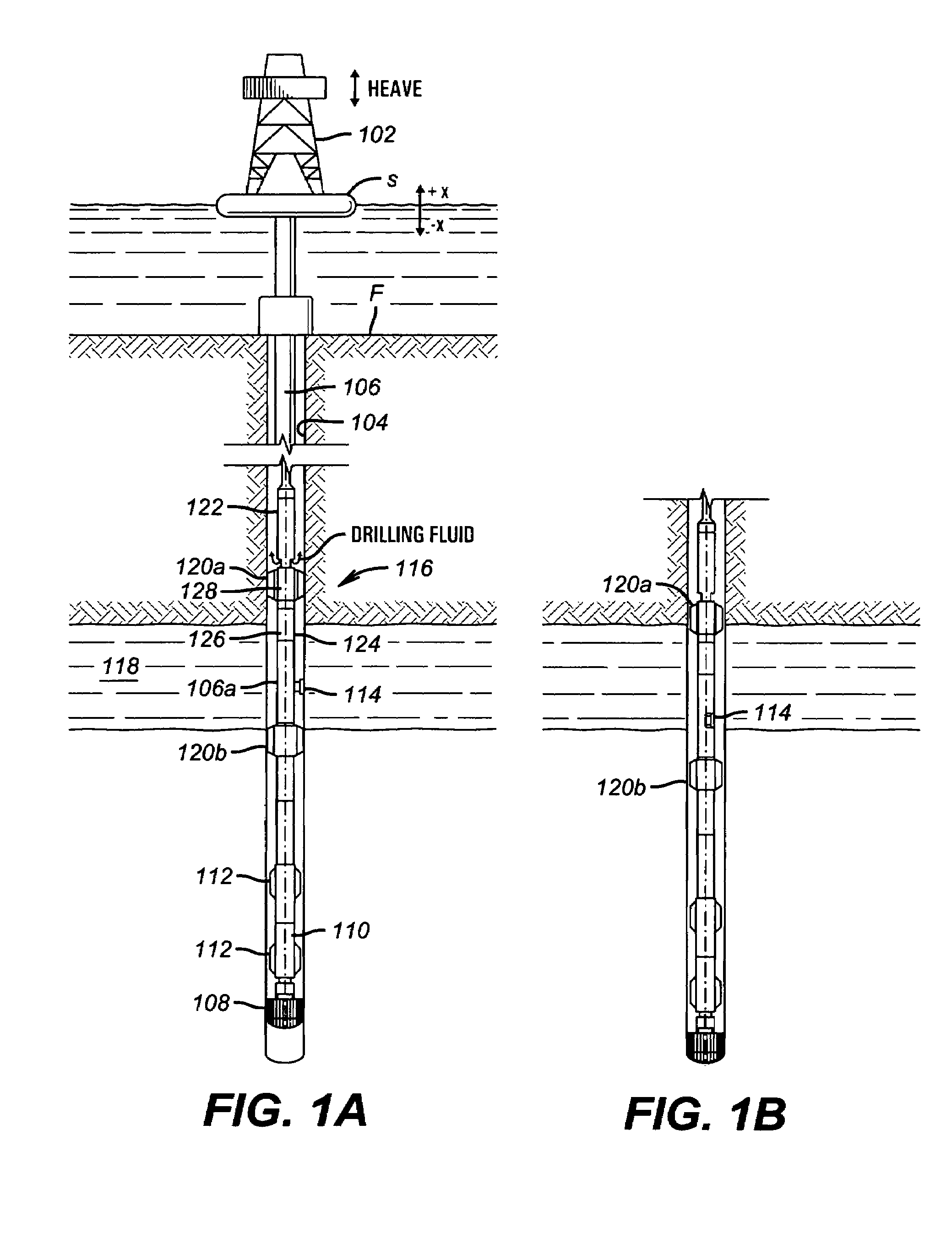
[0027]Referring to FIG. 1, a typical drilling rig 102 with a well borehole 104 extending therefrom is illustrated, as is well understood by those of ordinary skill in the art. The drilling rig 102 has a work string 106, which in the embodiment shown is a drill string. The work string 106 has attached thereto a drill bit 108 for drilling the well borehole 104. The present invention is also useful in other types of work strings, and it is useful with jointed tubing as well as coiled tubing or other small diameter work string such as snubbing pipe. Therefore, the term “work string” as used herein includes each of these several types of work string. FIG. 1 depicts the drilling rig 102 positioned on a drill ship S with a riser extending from the drilling ship S to the sea floor F. If applicable, the work string 106 can have a downhole drill motor 110 for rotating the drill bit 108. The drill bit might be rotated using a surface motor rotating a drill pipe. Fixed ribs or stabilizers 112 a...


PUM


Abstract

An apparatus and method for isolating a downhole tool section from hydraulic and mechanical noise. Anchoring grippers are used in conjunction with a fluid diverter valve to anchor the tool section to a borehole wall and divert fluid flowing in the drill string away from sensitive test equipment during formation testing.

Description

CROSS REFERENCE TO RELATED APPLICATIONS[0001]This application is continuation of the U.S. patent application having the Ser. No. 10 / 465,173 filed Jun. 19, 2003 now abandoned, which application is a continuation-in-part of U.S. patent application Ser. No. 09 / 703,645 filed Nov. 1, 2000 now U.S. Pat. No. 6,581,455. All prior applications being hereby fully incorporated herein by reference.BACKGROUND OF THE INVENTION[0002]1. Field of the Invention[0003]This invention relates to the testing of underground formations or reservoirs. More particularly, this invention relates to a method and apparatus for isolating a downhole test tool from vibration and noise due to heave and / or drilling fluid circulation during formation testing.[0004]2. Description of the Related Art[0005]While drilling a well for commercial development of hydrocarbon reserves, several subterranean reservoirs and formations are encountered. In order to discover information about the formations, such as whether the reservo...

Claims


Application Information

Patent Timeline
Patent Type & Authority Patents(United States)
IPC IPC(8): E21B47/08E21B44/00E21B47/01E21B49/08
CPCE21B47/01E21B49/08E21B49/088E21B21/10E21B23/01E21B47/00
Inventor MEISTER, MATTHIASKRUEGER, SVENLISS, CHRISTIAN
Owner BAKER HUGHES HLDG LLC
Why Eureka
Try Eureka