Fuel injection system having electric low-pressure pump

a fuel injection system and low-pressure pump technology, which is applied in the direction of fuel injecting pumps, electric control, machines/engines, etc., can solve the problems of insufficient fuel supply in a low-rotation speed period, fuel pump for filling the fuel passage is unnecessary, and the low-pressure pump cannot supply a larger quantity of fuel

Inactive Publication Date: 2007-04-24
DENSO CORP
View PDF17 Cites 35 Cited by
  • Summary
  • Abstract
  • Description
  • Claims
  • Application Information

AI Technical Summary

Benefits of technology

[0025]It is therefore an object of the present invention to provide a fuel injection system capable of reducing wasteful fuel supply of an electric low-pressure pump and power consumption of an electric actuator driving the low-pressure pump.
[0026]It is another object of the present invention to provide a fuel injection system using an electric low-pressure pump capable of quickly reducing a common rail pressure when the common rail pressure needs to be reduced.
[0029]Thus, the energization amount of the electric actuator driving the low-pressure pump can be regulated in accordance with a fuel quantity required by the engine. As a result, power consumption of the electric actuator can be reduced and wasteful fuel supply of the low-pressure pump can be reduced.
[0031]Thus, the fuel supply of the low-pressure pump can be stopped when the common rail pressure needs to be reduced quickly, for instance, when an abnormally high common rail pressure occurs. As a result, an increase of combustion noise and the like can be prevented by quickly reducing the common rail pressure.
[0034]Thus, by controlling the valve opening degree of the suction control valve in accordance with the sensing signal outputted by the low-pressure pump supply pressure sensing means, the fuel supply quantity supplied by the high-pressure pump to the engine can be substantially conformed to the fuel quantity required by the engine even if the fuel supply quantity of the low-pressure pump changes with time.

Problems solved by technology

First, the engine-driven low-pressure pump cannot supply a larger quantity of the fuel than a quantity corresponding to the engine rotation speed.
Therefore, there is a possibility that the fuel supply becomes deficient in a low-rotation speed period occurring immediately after a start of the engine, for instance.
Secondly, since the engine-driven low-pressure pump is attached to the end of the rotary shaft of the high-pressure pump, the system requires another pump for filling a fuel passage leading from the fuel tank to the low-pressure pump with the fuel when the engine is restarted after an engine stall or when the engine is shipped.
Therefore, the fuel pump for filling the fuel passage is unnecessary.
Therefore, the fuel supply of the electric low-pressure pump 100 of the related art is wasteful and power consumption of the electric actuator is large.
As a result, there is a possibility that a size of an alternator needs to be enlarged.
If an abnormally high common rail pressure occurs or if reduction of the common rail pressure delays as a result, there is a possibility that combustion noise increases.
As a result, there is a possibility that a difference between the fuel supply quantity supplied to the engine and the fuel quantity required by the engine increases, and exhaust gas characteristics and the like are deteriorated.

Method used


Image

  • Fuel injection system having electric low-pressure pump
  • Fuel injection system having electric low-pressure pump
  • Fuel injection system having electric low-pressure pump

Examples


first embodiment

[0043](First Embodiment)

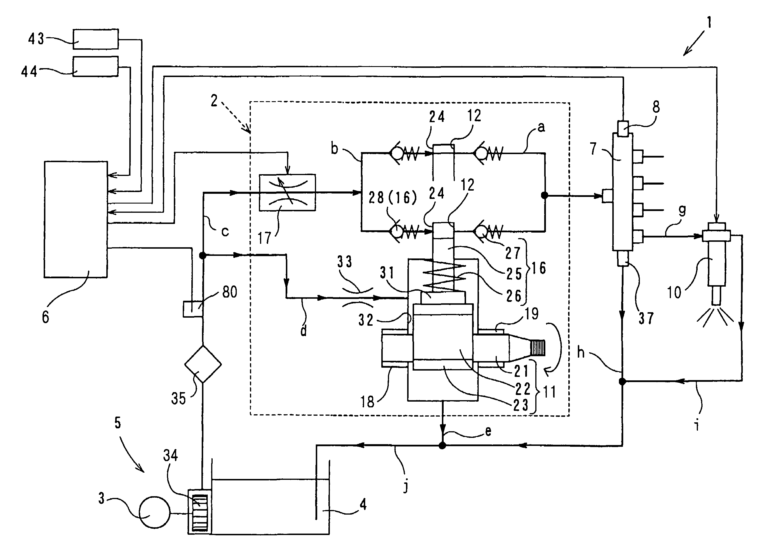
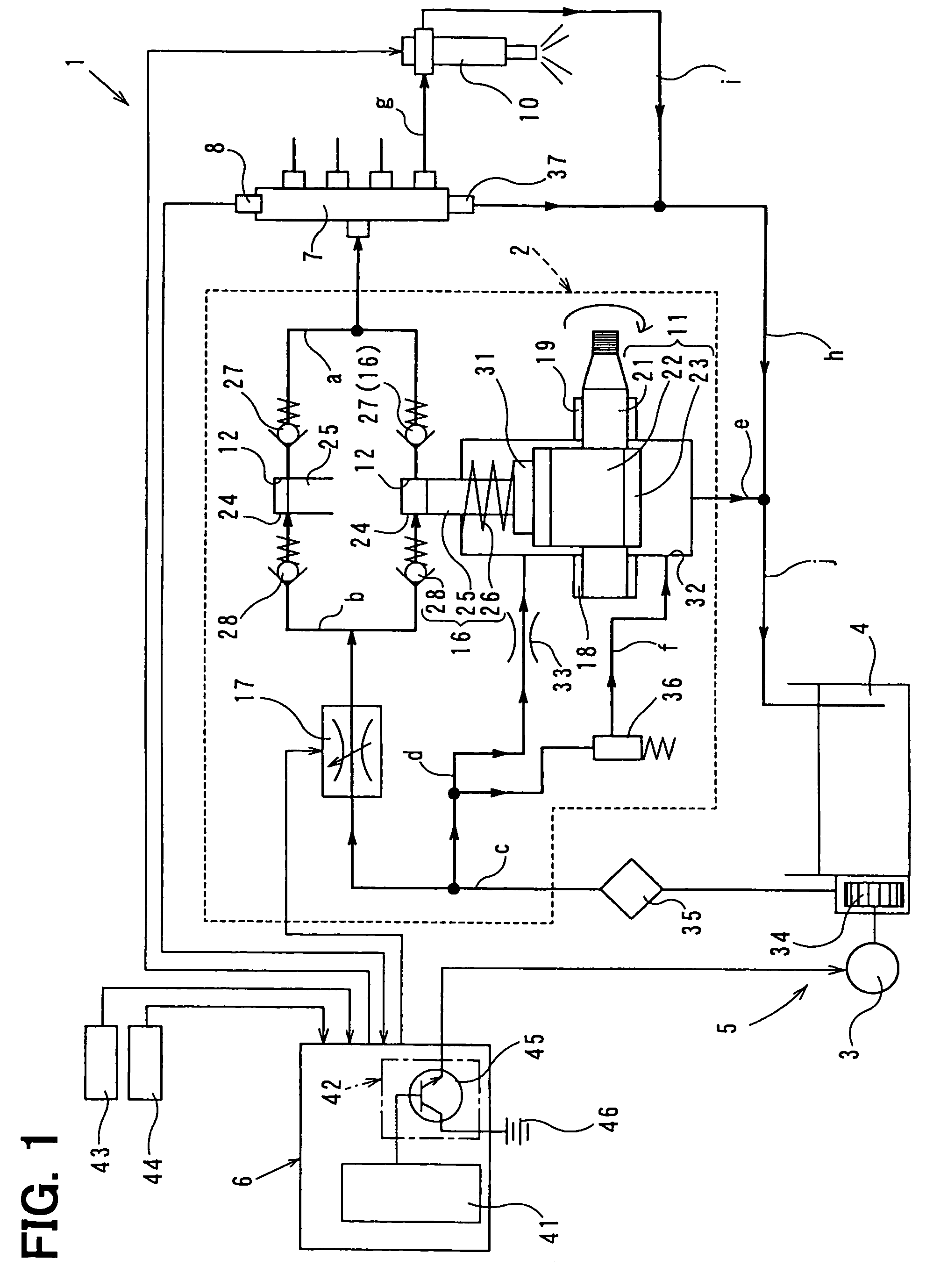
[0044]Referring to FIG. 1, a fuel injection system 1 according to a first embodiment of the present invention is illustrated.

[0045]As shown in FIG. 1, the fuel injection system 1 includes a high-pressure pump 2, a low-pressure pump 5, controlling means 6, a common rail 7 and common rail pressure sensing means 8. The high-pressure pump 2 pressurizes fuel to a high pressure and supplies the fuel to an engine. The low-pressure pump 5 is driven by an electric motor 3 as an electric actuator. Thus, the low-pressure pump 5 draws the fuel from a fuel tank 4 and supplies the fuel to the high-pressure pump 2. The controlling means 6 controls the fuel injection system 1. The controlling means 6 controls a fuel supply quantity of the low-pressure pump 5 by regulating an energization amount of the electric motor 3. The common rail 7 accumulates the fuel, which is supplied from the high-pressure pump 2, in a high-pressure state. The common rail pressure sensing means 8 se...

second embodiment

[0065](Second Embodiment)

[0066]Next, a fuel injection system 1 according to a second embodiment of the present invention will be explained based on FIG. 3.

[0067]The ECU 41 of the fuel injection system 1 of the second embodiment synthesizes a motor drive signal for driving the electric motor 3 and outputs the motor drive signal to the low-pressure pump drive circuit 42 when the fuel needs to be pressure-fed to the common rail 7. Responsive to the motor drive signal, the transistor 45 included in the low-pressure pump drive circuit 42 for energizing the electric motor 3 operates to energize the electric motor 3 with the use of the battery 46. Thus, the impeller 34 rotates at a predetermined rotation speed and a predetermined quantity of the fuel is supplied by the low-pressure pump 5.

[0068]If the ECU 41 determines that the state of the fuel injection system 1 is in a common rail pressure reduction period based on a transition of the injection quantity command value and the like, the E...

third embodiment

[0074](Third Embodiment)

[0075]Next, a fuel injection system 1 according to a third embodiment of the present invention will be explained based on FIGS. 4 and 5.

[0076]The fuel injection system 1 of the third embodiment shown in FIG. 4 includes low-pressure pump supply pressure sensing means 80 for sensing the fuel supply pressure of the low-pressure pump 5. The controlling means 6 controls the valve opening degree of the SCV 17 based on a sensing signal outputted by the low-pressure pump supply pressure sensing means 80.

[0077]The low-pressure pump supply pressure sensing means 80 is a publicly known pressure sensor attached to the fuel passage “c” between the fuel filter 35 and the SCV 17. The low-pressure pump supply pressure sensing means 80 senses the fuel pressure in the fuel passage “c”, or the supply pressure (a low-pressure pump supply pressure) of the low-pressure pump 5 on the downstream side of the fuel filter 35.

[0078]The controlling means 6 of the third embodiment control...


PUM


Abstract

Controlling means of a fuel injection system regulates an energization amount of an electric motor in accordance with a sensing signal outputted from common rail pressure sensing means. Thus, the controlling means controls a fuel supply quantity of a low-pressure pump. Thus, power consumption of the electric motor driving the low-pressure pump can be regulated in accordance with a pressure-feeding quantity of a high-pressure pump. As a result, the power consumption of the electric motor can be reduced and wasteful fuel supply of the low-pressure pump can be reduced.

Description

CROSS REFERENCE TO RELATED APPLICATION[0001]This application is based on and incorporates herein by reference Japanese Patent Applications No. 2004-69465 filed on Mar. 11, 2004, No. 2004-69518 filed on Mar. 11, 2004 and No. 2004-69576 filed on Mar. 11, 2004.BACKGROUND OF THE INVENTION[0002]1. Field of the Invention[0003]The present invention relates to a fuel injection system for supplying fuel into an engine by injection. Specifically, the present invention relates to a fuel injection system, which draws fuel from a fuel tank with the use of an electric actuator such as an electric motor.[0004]2. Description of Related Art[0005]A fuel injection system for supplying fuel to an engine by injection includes a high-pressure pump, which pressurizes the fuel to a high pressure and supplies the fuel to the engine through injection valves (injectors), and a low-pressure pump, which draws the fuel from a fuel tank and supplies the fuel to the high-pressure pump. The high-pressure pump has a...

Claims


Application Information

Patent Timeline
Patent Type & Authority Patents(United States)
IPC IPC(8): F02M37/04F02D41/38F02M59/20F02M59/34F02M63/00
CPCF02D41/22F02D41/3082F02D41/3854F02D41/3845F02M37/08F02M59/205F02M59/34F02M63/0225F02D2041/224F02D2250/31
Inventor UTSUMI, YASUTAKA
Owner DENSO CORP
Why Eureka
Try Eureka