Conveyor with center-actuatable gripper, and related conveyor link

a conveyor and center-actuation technology, applied in the direction of charging, lighting and heating apparatus, furniture, etc., can solve the problems of side effects, inability to achieve, disfavored frictional or high frictional surface,

Inactive Publication Date: 2007-04-24
ILLINOIS TOOL WORKS INC
View PDF229 Cites 16 Cited by
  • Summary
  • Abstract
  • Description
  • Claims
  • Application Information

AI Technical Summary

Problems solved by technology

Although the application of a friction surface element will minimize the aforementioned problems associated with the transport of goods, it may also create side-effect problems.
Often times it is desired to specifically locate an object on a conveyor belt, and this cannot be accomplished if the object on a high friction surface is not initially placed in the desired location.
Further, it can also be the case in a particular application that a frictional or a high frictional surface is disfavored.
Having a heavy object on a high friction surface would necessitate the need to generate increased amounts of force to move the object from the conveyor belt, or would at least impede movement of the object from the belt.
Another problem associated with some conveyor systems is vibration which causes objects to be rotated from one orientation to another.
Although effective, this solution can be impractical in certain parts of the conveying system in which spatial constraints do not allow for the installation of guide rails.

Method used


Image

  • Conveyor with center-actuatable gripper, and related conveyor link
  • Conveyor with center-actuatable gripper, and related conveyor link
  • Conveyor with center-actuatable gripper, and related conveyor link

Examples


third embodiment

[0072]Reference will now be made in detail to embodiments of the invention, one or more examples of which are illustrated in the drawings. Each example is provided by way of explanation of the invention, and not meant as a limitation of the invention. For example, features illustrated or described as part of one embodiment can be used with another embodiment to yield still a It is intended that the present invention include these and other modifications and variations. In discussing various embodiments, like or similar reference numerals are used below with like or similar parts of various embodiments.

[0073]As shown in the various figures, numerous embodiments of a gripper conveyor and conveyor link with a gripping member are disclosed. It should be understood that the present invention encompasses both a gripper conveyor chain-type structure, and individual links for such a chain. It should also be understood that various different methods of attaching such links together into a c...

first embodiment

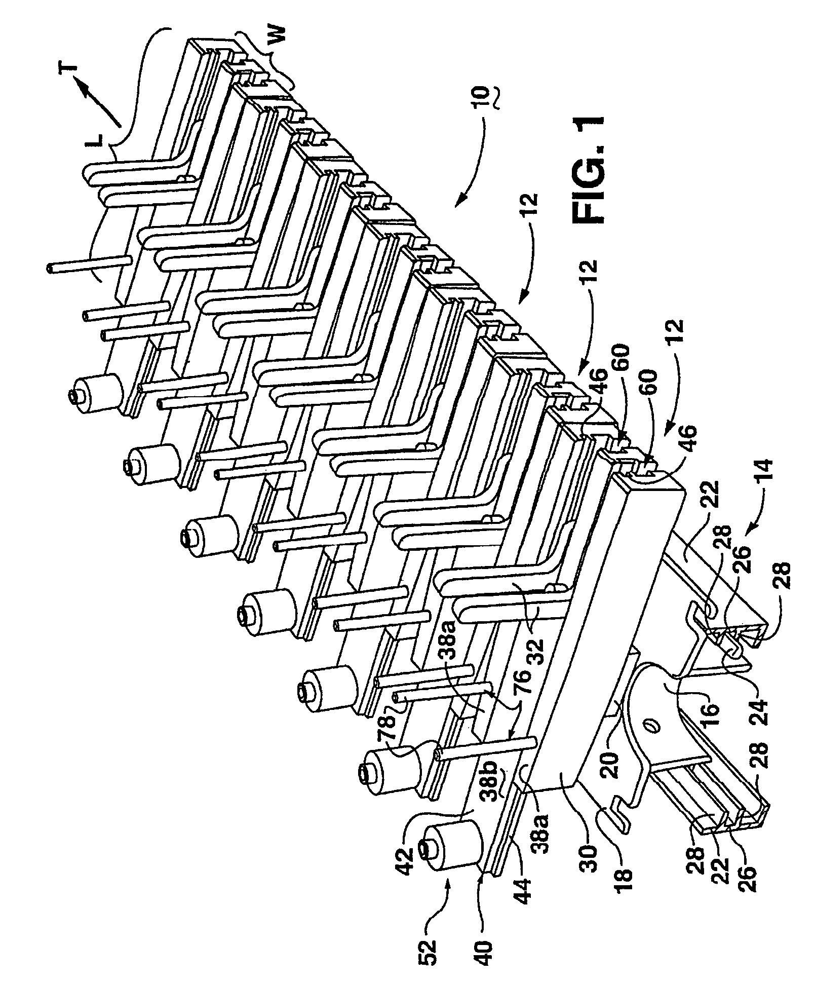
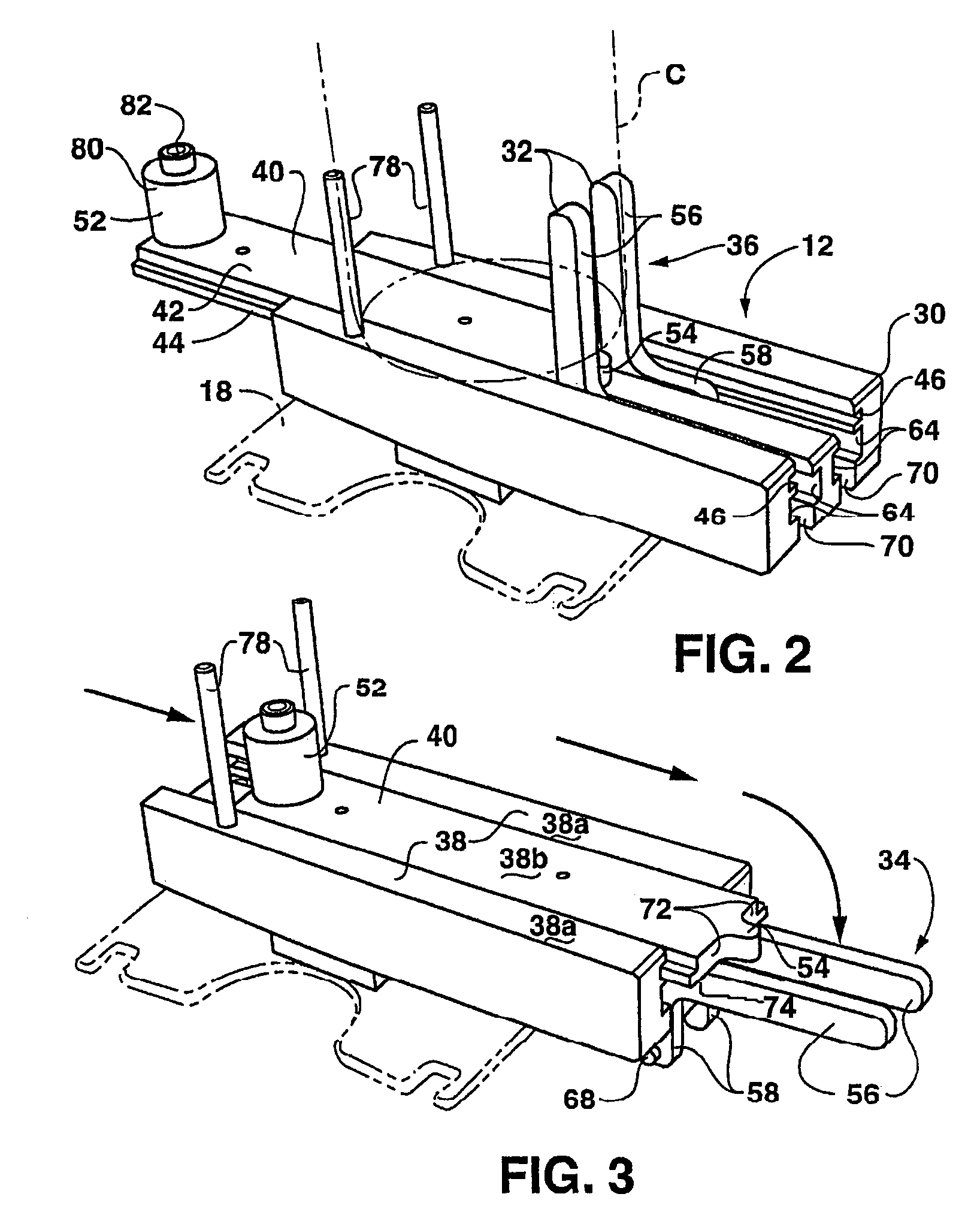
[0074]With particular reference to FIGS. 1–8, a gripper conveyor and conveyor link are shown. According to this embodiment of the invention, a conveyor 10 includes a plurality of links 12 and a drive mechanism 14. As illustrated in FIG. 1, drive mechanism 14 includes a knuckle conveyor 16 attached to a platform member 18, which may be constructed as set forth in U.S. Pat. No. 6,601,697 or in various other ways. It should be understood that drive mechanism 14 can have many shapes and forms according to the present invention. For example, instead of knuckle conveyor 16, other types of conveyors, belts, or chains such as roller chains, or roller chains with attachments, could be used for drive mechanism 14.

[0075]In the example shown, knuckle conveyor 16 is driven within rails 22, and is guided by flanges 24 extending from knuckle conveyor 16 into channels 26 defined by walls 28 of rails 22. As is known in the art, the drive mechanism may traverse a straight or curved line from one end ...


PUM

PropertyMeasurementUnit
lengthaaaaaaaaaa
widthaaaaaaaaaa
tangential forcesaaaaaaaaaa

Abstract

A conveyor is disclosed suitable for conveying objects along a transport direction. The conveyor includes a plurality of connected links, each link having a length extending across the direction of transport and a width extending along the direction of transport. Each link has a conveying surface and at least one movable gripping member extending from the conveying surface of the link. Each gripping member is movable from a first opened position to a second gripping position. The gripping members each include a gripping arm having a pivot point, a gripping end spaced from the pivot point, and a cam follower extending outward from the gripping arm between the pivot point and the gripping end. The gripping arm is located so as to be able to contact one of the objects via the gripping end when the gripping member is in the second position to hold the object relative to the link during transport. Each link includes at least one spring member urging the gripping members toward the second position. The links may be connected by universal joints, and may have two opposed movable gripping members. Related conveyor and link designs are also disclosed.

Description

RELATED APPLICATIONS[0001]The present application is a continuation-in-part application claiming priority under 35 U.S.C. § 120 to U.S. patent application Ser. No. 10 / 847,214, entitled Conveyor With Opposed Spring-Loaded Grippers, and Related Conveyor Link, filed May 17, 2004, and U.S. patent applications Ser. No. 10 / 712,405 now U.S. Pat. No. 7,021,453, entitled Conveyor with Gear Mechanism Gripper and Related Conveyor Link, Ser. No. 10 / 712,406 now U.S. Pat. No. 7,036,658, entitled Gripper Conveyor with Clear Conveying Path and Related Conveyor Link, and Ser. No. 10 / 712,407 now U.S. Pat. No. 7,055,676, entitled Conveyor with Movable Gripper and Related Conveyor Link, all filed Nov. 13, 2003, and assigned to the owner of the present application. These four patent applications are incorporated by reference herein in their entireties for all purposes.FIELD OF THE INVENTION[0002]The present invention relates generally to a conveyor and a link for such a conveyor including at least one m...

Claims


Application Information

Patent Timeline
Patent Type & Authority Patents(United States)
IPC IPC(8): B65G25/00B65G17/32B65G47/86
CPCB65G17/323B65G47/842B65G2201/0244B65G2201/0247
Inventor HARTNESS, THOMAS P.HARTNESS, III, WILLIAM R.DAVIDSON, MARK W.BRENNAN, FRANKBEESLEY, ROBERT C.
Owner ILLINOIS TOOL WORKS INC
Why Eureka
Try Eureka