Particle accelerator having wide energy control range

a particle accelerator and energy control technology, applied in the direction of instruments, mass spectrometers, beam deviation/focusing by electric/magnetic means, etc., can solve the problem of large energy spread, insufficient collection of data, and inability to identify or discriminate,

Inactive Publication Date: 2007-04-24
SCANTECHIBS IP HLDG
View PDF4 Cites 24 Cited by
  • Summary
  • Abstract
  • Description
  • Claims
  • Application Information

AI Technical Summary

Benefits of technology

[0011]Broadly described, the present invention comprises a particle accelerator system, including apparatuses and methods, for producing a charged particle beam having pulses of charged particles that have different energy levels from pulse to pulse. More particularly, the present invention comprises a particle accelerator system, including apparatuses and methods, for producing a charged particle beam having pulses of charged particles that have different energy levels from pulse to pulse by independently adjusting the amount of RF power delivered to first and second accelerating sections thereof without adjusting the amount of RF power generated by an RF source thereof. Such independent adjustment of the delivery of RF power enables the amount of RF power provided to the first accelerating section to be maintained at an appropriate level for optimal electron capturing therein and for producing a tightly bunched beam of electrons having different energy levels from pulse to pulse, while enabling the amount of RF power provided to the second accelerating section to be varied in order to vary the energy levels of the charged particles of the charged particle beam from pulse to pulse.
[0012]According to a first embodiment, the particle accelerator system includes an RF drive system having an RF source coupled to an amplifier and a phase shifter so as to enable adjustment of the accelerating field created in an accelerating section without adjusting the power output from the RF source. The ratio of the amplitudes of the RF waves provided to the accelerating sections is regulated by shifting the phase of the RF waves delivered to the second accelerating section relative to the phase of the RF waves of the first accelerating section with a phase shifter. Because the magnitude, or strength, of the accelerating fields in the accelerating sections depends on the RF power provided, respectively, to each of the accelerating sections and because the RF power provided to each of the accelerating sections is based on the amplitudes of the RF waves provided thereto, shifting the phase of the RF waves for the second accelerating section enables changing of the RF power provided to the second accelerating section and of the magnitude of the accelerating field of the second accelerating section relative to the magnitude of the accelerating field of the first accelerating section.
[0015]The RF power supplied to the second accelerating section in low energy mode is significantly lower than the RF power supplied to the second accelerating section in the high energy mode. Because the RF power supplied to the second accelerating section is decreased in the low energy mode and because the injection current is increased in the low energy mode, the energy provided to the second accelerating section is lower and, hence, the strength of the accelerating field in the second accelerating section is lower than in high energy mode. As a consequence, the incremental energy increase in the energy level of the charged particles in the second accelerating section in low energy mode is substantially lower than the incremental energy increase in the energy level of the charged particles in the second accelerating section in high energy mode.

Problems solved by technology

In recent years, the proliferation of international terrorism has spurred concerns over the contents of cargo containers which are received from foreign countries by land or sea as such cargo containers may include explosives, weapons of mass destruction, or other items that may be harmful to individuals and / or property.
However, the collected data is inadequate to identify or discriminate between different materials present in the cargo containers and, hence, such inspection systems provide only visual images of the contents of cargo containers.
Unfortunately, the generation of such a beam of highly energized electrons having different energy spectra has proven to be problematic.
However, varying the RF power in this manner causes the beam produced by the accelerator to have a large energy spread, and consequently, the efficiency of the particle accelerator is decreased.
The accelerator, however, suffers from the same disadvantages as suffered by the accelerator of the first approach described above.
Due at least in part to the weakened accelerating electric field, there is a decrease in the overall efficiency of the accelerator.
Unfortunately, this approach is also inadequate because of the resulting ungrounded electromagnetic energy loss in the attenuator at amplitude control and in the standing wave accelerating section at phase control.
Although adjustment of the rods enables the output particle energy to be varied, the mechanical process by which the rods are adjusted is extremely slow and is inadequate for applications that require an output beam of electrons that must be rapidly varied between energy levels.
Moreover, there is an inherent risk of sparking during sliding of the rods within the cavity.

Method used


Image

  • Particle accelerator having wide energy control range
  • Particle accelerator having wide energy control range
  • Particle accelerator having wide energy control range

Examples


Embodiment Construction

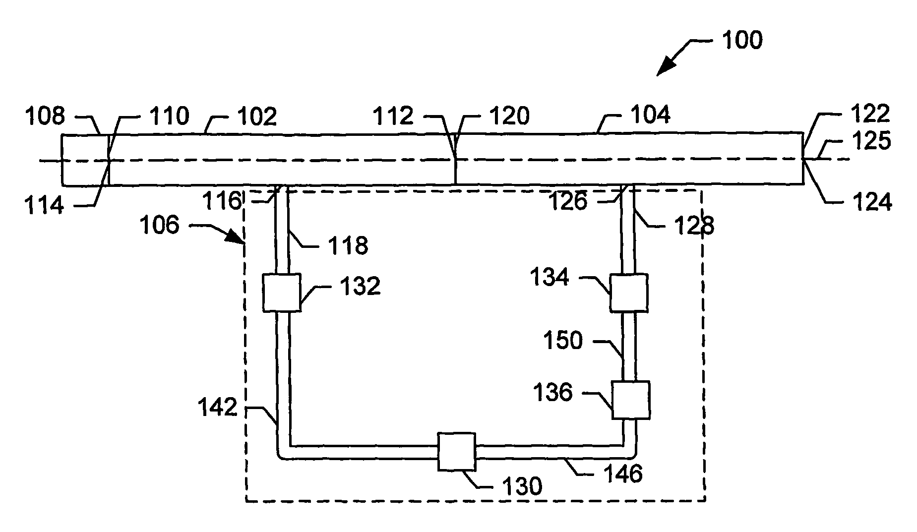
[0030]Referring now to the drawings in which like numerals represent like elements or steps throughout the several views, FIG. 1 displays a schematic block diagram representation of a particle accelerator system 100 in accordance with a first embodiment of the present invention. The particle accelerator system 100 comprises a first accelerating section 102, a second accelerating section 104, an RF drive subsystem 106, and an injector 108. Preferably, the first and second accelerating sections 102, 104 comprise standing-wave accelerating sections 102, 104 having a biperiodic accelerating structure which are operable to accelerate charged particles through the transfer of energy from RF power provided to the accelerating sections 102, 104 by the RF drive subsystem 106.

[0031]The first accelerating section 102 has a first end 110 and a second end 112. The injector 108 is positioned proximate the first end 110 of the first accelerating section 102 and is connected to an input port 114 of...


PUM


Abstract

A particle accelerator system for producing a charged particle beam having pulses of charged particles that have different energy levels from pulse to pulse. The system enables independent adjustment of the RF power delivered to first and second accelerating sections thereof without adjustment of the RF power generated by an RF source. Such independent adjustment enables the RF power provided to the first accelerating section to be maintained at a level appropriate for optimal particle capturing therein and for producing a tightly bunched beam of particles having different energy levels from pulse to pulse, while enabling the RF power provided to the second accelerating section to be varied in order to vary the energy levels of the charged particles of the charged particle beam from pulse to pulse.

Description

CROSS REFERENCE TO RELATED APPLICATION[0001]This application claims the benefit of priority to U.S. provisional application Ser. No. 60 / 414,132, which is entitled “Wide Energy Control Range Particle Accelerator” and was filed on Sep. 27, 2002.FIELD OF THE INVENTION[0002]The invention relates, generally, to the field of charged particle accelerators, and, more specifically, to charged particle accelerators capable of producing pulses of charged particles having different energy levels.BACKGROUND OF THE INVENTION[0003]In recent years, the proliferation of international terrorism has spurred concerns over the contents of cargo containers which are received from foreign countries by land or sea as such cargo containers may include explosives, weapons of mass destruction, or other items that may be harmful to individuals and / or property. Existing inspection systems utilize high energy X-rays to produce visual images of the contents of cargo containers. The high energy X-rays are, typical...

Claims


Application Information

Patent Timeline
Patent Type & Authority Patents(United States)
IPC IPC(8): H01J23/00G21K5/04H01J3/14H01S1/00H05H7/22H05H15/00
CPCG21K5/04H05H7/22H05H15/00
Inventor ZAVADTSEV, ALEXANDRE A.BOWSER, GARY F.
Owner SCANTECHIBS IP HLDG
Why Eureka
Try Eureka